Straight Segments creation and customization
29 Nov 20247 minutes to read
The path of the Connector is defined with a collection of Segments and each segment represents a line between two points. By default, connector type will be identified using the value of DefaultConnectorType property of Diagram. It changes the entire connectors type in the diagram but when you define the segment then the particular connector will be displayed based on the segment created. There are four types of segments,
- Straight
- Orthogonal
- Cubic curve
- Quadratic curve
Straight segments
Straight segment allows to create a straight-line connector between two end points or two nodes. To create a straight line, specify the segment as StraightSegment and add it to the connector’s segments collection.
<!--Initialize the Sfdiagram-->
<syncfusion:SfDiagram x:Name="diagram">
    <syncfusion:SfDiagram.Connectors>
        <!--Initialize the Connector Collection-->
        <syncfusion:ConnectorCollection>
            <!--Initialize the Connector-->
            <syncfusion:ConnectorViewModel SourcePoint="100,100" TargetPoint="200,200" >
                <syncfusion:ConnectorViewModel.Segments>
                    <!--Initialize the connector segment collection-->
                    <syncfusion:ConnectorSegments>
                        <!--Specify the segment as straight segment-->
                        <syncfusion:StraightSegment/>
                    </syncfusion:ConnectorSegments>
                </syncfusion:ConnectorViewModel.Segments>
            </syncfusion:ConnectorViewModel>
        </syncfusion:ConnectorCollection>
    </syncfusion:SfDiagram.Connectors>
</syncfusion:SfDiagram>
//Initialize the SfDiagram
SfDiagram diagram = new SfDiagram();
//Define the Connector
ConnectorViewModel connector = new ConnectorViewModel()
{
SourcePoint = new Point(100, 100),
TargetPoint = new Point(200, 200),
//Initialize the connector segment collection
Segments = new ObservableCollection<IConnectorSegment>()
{
//Specify the segment as straight segment
new StraightSegment()
}
};
//Adding Connector to Collection
(diagram.Connectors as ConnectorCollection).Add(connector);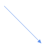
Editing straight segments
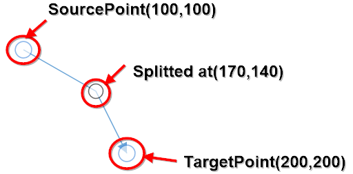
A straight-line connector can be edited by adding a new StraightSegment into the Segments collections of a Connector.
Straight segments can be split into multiple straight lines using Point property of StraightSegment class.
<syncfusion:ConnectorViewModel SourcePoint="100,100" TargetPoint="200,200">
    <syncfusion:ConnectorViewModel.Segments>
        <syncfusion:ConnectorSegments>
            <!--Specify the point to split the segment-->
            <syncfusion:StraightSegment Point="170,140"/>
        </syncfusion:ConnectorSegments>
    </syncfusion:ConnectorViewModel.Segments>
</syncfusion:ConnectorViewModel>
//create the connector with straight segments
ConnectorViewModel connector = new ConnectorViewModel()
{
SourcePoint = new Point(100,100),
TargetPoint = new Point(200,200),
Segments = new ObservableCollection<IConnectorSegment>()
{
new StraightSegment()
{
//Specify the point to split the segment
Point = new Point(170,140),
},
}
};
How to add or remove the straight segments at run time
Straight segments can be split into multiple straight segments interactively by clicking on the segemnts. This can be achieved by using AddRemoveStraightSegmentArgs class and its properties.
AddRemoveStraightSegmentArgs class is having below properties,
- Point: To specify the splitting point on the segment
- SegmentEditing: To specify that segments are going to be added or removed
- HitPadding: To specify the vicinity area around the connector
Following code example illustrates how to add or remove straight segements when click on any point of the segment,
//Initialize the SfDiagram
SfDiagram diagram = new SfDiagram();
//Register the item tap event of diagram
(diagram.Info as IGraphInfo).ItemTappedEvent += Diagram_ItemTappedEvent;

private void Diagram_ItemTappedEvent(object sender, DiagramEventArgs args)
{
    if (args.Item is IConnector)
    {
        //Getting the mouse point while tap on the connector
        Point pp = ((args as ItemTappedEventArgs).MouseEventArgs as MouseEventArgs).GetPosition(diagram.Page);
        //Specify the editing point, editing type and hit padding value
        AddRemoveStraightSegmentArgs addremoveargs = new AddRemoveStraightSegmentArgs()
        {
            Point = pp,
            SegmentEditing = SegmentEditing.Add,
            HitPadding = 5
        };

        //Method to add or remove the segment
        ((args.Item as IConnector).Info as IConnectorInfo).EditSegment(addremoveargs);
    }
}| SegmentEditing value | Description | Output |
|---|---|---|
| SegmentEditing.Add | New segment will be added at the tapped point |  |
| SegmentEditing.Remove | Exisiting segment will be deleted at the tapped point |  |
| SegmentEditing.Toggle | New segment will be added at the tapped point if there is no segment at that point or exisiting segment will be deleted |  |
NOTE
Segment splitting will be supported only for straight segments.
Find the Straight segment sample to depict the Straight segment.
See Also
How to detect or get notification when editing the thumbs of connector?