How can I help you?
Port in WPF Diagram (SfDiagram)
29 Jan 202522 minutes to read
Port is a special connection point on a Node or Connector that you can glue the connectors. When you glue a connector to a node or port, they stay connected, even if one of the node is moved.
Connections
There are two main types of connections: dynamic and port. The difference between these two connections is whether or not a connector remains glued to a specific connection point when you move the attached node or connector.
A dynamic connection is one where the connector will move around the node as you move the node. Diagram will always ensure the connector is the shortest, most direct line possible. You can create a dynamic connection by selecting the entire node (rather than the port) and connect it to another shape (rather than to a port).
A port connection is one where the connector is glued on the connection point of a node. When you move this node, the connector will always remain attached to the same connection point. You can create a port connection by connecting a specific port on one node to another port on another shape.
SfDiagram supports three types of ports: Node Port, Connector Port, and DockPort.
Node port
A port on a node can be created using the instance of NodePort object. The NodeOffsetX and NodeOffsetY properties of NodePort class is used to specify the position of the port on a node.
<!--Style for Node-->
<Style TargetType="Syncfusion:Node">
  <Setter Property="ShapeStyle">
    <Setter.Value>
      <Style TargetType="Path">
        <Setter Property="Fill" Value="#FF5B9BD5"/>
        <Setter Property="Stretch" Value="Fill"/>
        <Setter Property="Stroke" Value="#FFEDF1F6"/>
      </Style>
    </Setter.Value>
  </Setter>
</Style>

<!--style for NodePort-->
<Style TargetType="Syncfusion:NodePort">
  <Setter Property="Shape">
    <Setter.Value>
      <RectangleGeometry Rect="0,0,10,10"/>
    </Setter.Value>
  </Setter>
  <Setter Property="ShapeStyle">
    <Setter.Value>
      <Style TargetType="Path">
        <Setter Property="Stretch" Value="Fill"/>
        <Setter Property="Fill" Value="#FF808081"/>
      </Style>
    </Setter.Value>
  </Setter>
</Style>

<syncfusion:SfDiagram x:Name="diagram" PortVisibility="Visible">
  <!--Initializes the NodeCollection-->
  <syncfusion:SfDiagram.Nodes>
    <syncfusion:NodeCollection>
      <!--Initializes the Node-->
      <syncfusion:NodeViewModel UnitHeight="100" UnitWidth="100"
                                OffsetX="100" OffsetY="100"
                                Shape="{StaticResource Rectangle}">
        <!--Initialization of PortCollection-->
        <syncfusion:NodeViewModel.Ports>
          <syncfusion:PortCollection>
            <!--Initialization of NodePort-->
            <syncfusion:NodePortViewModel x:Name="port"/>
          </syncfusion:PortCollection>
        </syncfusion:NodeViewModel.Ports>
      </syncfusion:NodeViewModel>
    </syncfusion:NodeCollection>
  </syncfusion:SfDiagram.Nodes>
</syncfusion:SfDiagram>
//Define diagram
SfDiagram diagram = new SfDiagram();
//Initialize the visibility of the port as visible
diagram.PortVisibility = PortVisibility.Visible;
//Define Node's Collection
diagram.Nodes = new NodeCollection();
//Define Connector's Collection
diagram.Connectors = new ConnectorCollection();
//Create nodeviewmodel
NodeViewModel node = new NodeViewModel()
{
UnitHeight = 100,
UnitWidth = 100,
OffsetX = 300,
OffsetY = 300,
Shape = App.Current.Resources["Rectangle"],
};
//Define port to the PortCollection of the Node
(node.Ports as PortCollection).Add(new NodePortViewModel());
//Add node to the NodeCollection of the diagram
(diagram.Nodes as NodeCollection).Add(node);
//RootGrid is the instance of Mainwindow Grid
RootGrid.Children.Add(diagram);
NOTE
By default, port will be visible while dragging the connector thumb hover the diagram element where port presents within the diagram element. For more information , refer to the PortVisibility
NodeOffset
The NodeOffsetX and NodeOffsetY properties of port is used to position the port based on fractions. 0 represents Node’s top/left corner, 1 represents Node’s bottom/right corner, and 0.5 represents Node’s center point. Default value is (0.5, 0.5).
| Offset values | Output |
|---|---|
| (0,0) |  |
| (0,0.5) |  |
| (0,1) |  |
| (0.5,0) |  |
| (0.5,0.5) |  |
| (0.5,1) |  |
| (1,0) |  |
| (1,0.5) |  |
| (1,1) |  |
Displacement
The Displacement property is used to dislocate the port by the value given. By default, port will be in the center of the node. When you assign value to the Displacement property, port will be displaced from its position by displacment value. Default value is 0d.
<!--Displace the port 5pixel away from left side-->
<Syncfusion:NodePortViewModel x:Name="port" Displacement="5,0,0,0" UnitWidth="7" UnitHeight="7" NodeOffsetX="1" NodeOffsetY="0.5"/>
NodePortViewModel port = new NodePortViewModel()
{
UnitHeight = 7,
UnitWidth = 7,
NodeOffsetX = 1,
NodeOffsetY = 0.5,
//Displace the port 5pixel away from left side
Displacement = new Thickness(5,0,0,0)
};
Connector port
To specify and make connection with Connector at precise Length.
Define connector port
A port on a connector can be created using the instance of ConnectorPort object. The Length property of the ConnectorPort class is used to specify the position of the port on a connector path.
Find the common style for Connector and ConnectorPort.
<!--Style for the Connector-->
<Style TargetType="Syncfusion:Connector">
  <Setter Property="ConnectorGeometryStyle">
    <Setter.Value>
      <Style TargetType="Path">
        <Setter Property="Stroke" Value="#FF5B9BD5"></Setter>
        <Setter Property="StrokeThickness" Value="1"></Setter>
      </Style>
    </Setter.Value>
  </Setter>
  <Setter Property="TargetDecoratorStyle">
    <Setter.Value>
      <Style TargetType="Path">
        <Setter Property="Stroke" Value="#FF5B9BD5"></Setter>
        <Setter Property="StrokeThickness" Value="1"></Setter>
      </Style>
    </Setter.Value>
  </Setter>
</Style>
<!--Style For ConnectorPort-->
<Style TargetType="Syncfusion:ConnectorPort">
  <Setter Property="ShapeStyle">
    <Setter.Value>
      <Style TargetType="Path">
        <Setter Property="Fill" Value="#FF808081"/>
      </Style>
    </Setter.Value>
  </Setter>
  <Setter Property="Shape">
    <Setter.Value>
      <RectangleGeometry Rect="0,0,10,10"/>
    </Setter.Value>
  </Setter>
</Style>

<!--Initialize the sfdiagram-->
<syncfusion:SfDiagram x:Name="diagram" PortVisibility="Visible">
  <!--Initialize the ConnectorCollection-->
  <syncfusion:SfDiagram.Connectors>
    <syncfusion:ConnectorCollection>
      <!--Initialize the Connector-->
      <syncfusion:ConnectorViewModel SourcePoint="100,100" TargetPoint="200,200">
        <syncfusion:ConnectorViewModel.Ports>
          <!--Iitializes the PortCollection-->
          <syncfusion:PortCollection>
            <!--Initializes the ConnectorPort-->
            <syncfusion:ConnectorPortViewModel x:Name="Port"  Length="0.5"/>
          </syncfusion:PortCollection>
        </syncfusion:ConnectorViewModel.Ports>
      </syncfusion:ConnectorViewModel>
    </syncfusion:ConnectorCollection>
  </syncfusion:SfDiagram.Connectors>
</syncfusion:SfDiagram>
//Define diagram
SfDiagram diagram = new SfDiagram();
//Initialize the visibility of the port as visible
diagram.PortVisibility = PortVisibility.Visible;
//Define Connector Property
diagram.Connectors = new ConnectorCollection();
ConnectorViewModel connector = new ConnectorViewModel()
{
SourcePoint = new Point(100, 100),
TargetPoint = new Point(200, 200),
};
//Define port to the PortCollection of the connector
(connector.Ports as PortCollection).Add(new ConnectorPortViewModel());
//Adding Connector to Collection
(diagram.Connectors as ConnectorCollection).Add(connector);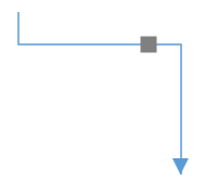
Length
The Length property of port is used to align the port based on fractions. 0 represents top/left corner, 1 represents bottom/right corner, and 0.5 represents half of width/height. Default value is 0.5.
| Length value | Output |
|---|---|
| 0 | 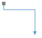 |
| 0.5 | 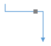 |
| 1 |  |
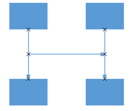
Dock port
DockPort is different from standard ports like NodePort and ConnectorPort. It is a placeholder that allows us to create connections at any point within it. Using DockPort, you can achieve lines of connecting points within the node boundary as shown in the following image.
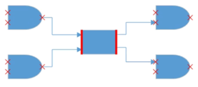
A DockPort on a node can be created using the instance of DockPort object. The SourcePoint and TargetPoint properties of DockPort allows you to define its start and end points.
<!--Style for DockPort-->
<Style TargetType="Syncfusion:DockPort">
  <Setter Property="ConnectorGeometryStyle">
    <Setter.Value>
      <Style TargetType="Path">
        <Setter Property="Stroke" Value="Black"></Setter>
        <Setter Property="StrokeThickness" Value="5"></Setter>
      </Style>
    </Setter.Value>
  </Setter>
</Style>

<!--Initializes the Node-->
<syncfusion:NodeViewModel x:Name="node" OffsetX="100" OffsetY="100"
                          UnitHeight="100" UnitWidth="100"
                          Shape="{StaticResource Rectangle}">
  <!--Initializes the PortCollection-->
  <syncfusion:NodeViewModel.Ports>
    <syncfusion:PortCollection>
      <!--Initializes the DockPort-->
      <syncfusion:DockPortViewModel x:Name="port"
                                    SourcePoint="0,1"
                                    TargetPoint="1,1"/>
    </syncfusion:PortCollection>
  </syncfusion:NodeViewModel.Ports>
</syncfusion:NodeViewModel>
//Create nodeviewmodel
NodeViewModel node = new NodeViewModel()
{
UnitHeight = 100,
UnitWidth = 100,
OffsetX = 100,
OffsetY = 100,
Shape = App.Current.Resources["Rectangle"]
};
//Initialize dockportviewmodel to the nodeviewmodel
(node.Ports as PortCollection).Add
(
new DockPortViewModel()
{
SourcePoint = new Point(0, 1),
TargetPoint = new Point(1, 1)
}
);
Geometry Style
The appearance of DockPort such as stroke and stroke thickness can be customized using the ConnectorGeometryStyle property.
<!--Style for DockPort-->
<Style TargetType="Syncfusion:DockPort">
  <Setter Property="ConnectorGeometryStyle">
    <Setter.Value>
      <Style TargetType="Path">
        <Setter Property="Stroke" Value="DarkOrange"></Setter>
        <Setter Property="StrokeThickness" Value="5"></Setter>
      </Style>
    </Setter.Value>
  </Setter>
</Style>
NOTE
To visualize the DockPort, it is must to specify the SourcePoint , TargetPoint, and ConnectorGeometryStyle properties.
Padding
Padding is used to leave space between the connector’s end point and the object to where it is connected. The ConnectorPadding property of port defines the space to be left between the port bounds and its edges. Default value is 0d.
<!--Declaring the ConnectorPadding value-->
<syncfusion:NodePortViewModel NodeOffsetX="0" NodeOffsetY="0.5"
                              ConnectorPadding="10"/>
NodePortViewModel nodePort = new NodePortViewModel()
{
//Declaring the ConnectorPadding value
ConnectorPadding = 10,
NodeOffsetX = 0,
NodeOffsetY = 0.5,
};
HitPadding
Connection can be made from or to nodes, connectors, port or on an empty area in a diagram. Making a connection with ports is usually difficult as thickness is usually small. To make it easy to connect, it should be possible to connect when the mouse comes near its vicinity area. The HitPadding property allows us to customize the vicinity area when connecting. The connector can be created by clicking and dragging to any point of hit padding of ports and can be dropped at any point of hit padding region of ports. Default value is 0d.
DockPortViewModel dockPort = new DockPortViewModel()
{
    Constraints=PortConstraints.Default & ~PortConstraints.InheritHitPadding,
    //Declaring the value for HitPadding
    HitPadding = 40,
    SourcePoint = new Point(1, 0),
    TargetPoint = new Point(1, 1),
};

NodePortViewModel nodePort = new NodePortViewModel()
{
    Constraints = PortConstraints.Default & ~PortConstraints.InheritHitPadding,
    //Declaring the value for HitPadding
    HitPadding = 40,
    NodeOffsetX = 0,
    NodeOffsetY = 0.5,
};
PortVisibility
The visibility of ports depends on the properties of MouseOver, Default, Collapse, MouseOverOnConnect, ValidConnection, and Visible.
| Property | Definition |
|---|---|
| MouseOver | Port is visible when mouse hover over the DiagramElement. |
| Default | Port is visible while dragging the connector thumb over the DiagramElement where port is present within the DiagramElement. |
| Collapse | Port is not visible for the DiagramElement. |
| MouseOverOnConnect | Port is visible while dragging the connector thumb over the DiagramElement where a port is present within the DiagramElement. |
| ValidConnection | Specifies to make the port visible when hovering over the DiagramElement and enable the PortConstraints as InConnect and OutConnect. |
| Visible | Port is always visible for the DiagramElement. |
To learn more about PortVisibility, refer to PortVisibility.
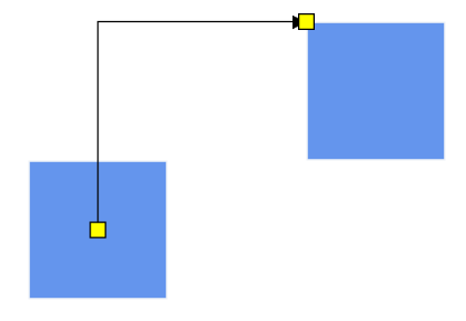
Connection direction
The ConnectionDirection is a port’s property, which allows users to specify the direction in which the connector’s connection to be established to a port. This property will be active only if the port constraints contains PortConstraints.ConnectionDirection. Default value is Auto.
<syncfusion:NodePortViewModel NodeOffsetX="0.5" NodeOffsetY="0.5" Constraints="Connectable,ConnectionDirection" ConnectionDirection="Right"/>NodePortViewModel port = new NodePortViewModel()
{
NodeOffsetX = 0.5,
NodeOffsetY = 0.5
};
port.Constraints = PortConstraints.Connectable | PortConstraints.ConnectionDirection;
//Specifying the direction in which connector need to connected to the port
port.ConnectionDirection = ConnectionDirection.Right;Before ConnectionDirection
After ConnectionDirection
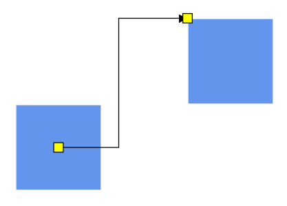
For more information , refer to ConnectionDirection
Appearance
-
The shape of the port can be changed by using its
shapeproperty. The shape can be any Built-In Shapes or any custom geometric path. -
The appearance of ports can be customized by using the
ShapeStyleproperty of the port. -
Customize the port size by using the
UnitWidthandUnitHeightproperties of port. -
The
PortVisibilityproperty allows you to define, when the port should be visible.
NOTE
For DockPort customization, refer to Geometry Style
<!--style for NodePort-->
<Style TargetType="Syncfusion:NodePort" >
  <Setter Property="Shape">
    <Setter.Value>
      <EllipseGeometry RadiusX="5" RadiusY="5"/>
    </Setter.Value>
  </Setter>
  <Setter Property="ShapeStyle">
    <Setter.Value>
      <Style TargetType="Path">
        <Setter Property="Fill" Value="Yellow"/>
      </Style>
    </Setter.Value>
  </Setter>
</Style>

<!--Initializes the NodePort-->
<syncfusion:NodePortViewModel x:Name="port" UnitWidth="7" UnitHeight="7"
                              NodeOffsetX="1" NodeOffsetY="0.5"/>
NodePortViewModel port = new NodePortViewModel()
{
UnitHeight = 7,
UnitWidth = 7,
NodeOffsetX=1,
NodeOffsetY=0.5
};
(node.Ports as PortCollection).Add(port);
Events
The PortChangedEvent will get invoked when you drag the port.
-
NodePort: The
PortChangedEventwill notify theOffsetXandOffsetYchanges with theirOldValueandNewValue. -
ConnectorPort: The
PortChangedEventwill notify theLengthchanges with theirOldValueandNewValue. -
DockPort: The
PortChangedEventwill notify theSourcePointandTargetPointchanges with theirOldValueandNewValue.
To explore about arguments, refer to PortChangedEvent
Constraints
The Constraints property allows you to enable or disable certain behaviors of ports. For more information about port constraints, refer to Port Constraints.
See Also
How to control the visibility of Ports?
How to connect only with port not with node?
How to validate the connection and port visibility (inport and outport) in the diagram?
How to customize the connection indicator style of node and port?
How to add multiple ports for the node?
How to decide whether to drag or draw a connection on port at runtime?
How to add ToolTip for Diagram objects of Node, NodePort in Diagram?
How to disable the animation while creating a connection in diagram?
How to create port at runtime through set tool?
How to override the default cursors while interact on diagram objects?
How to achieve zoom in or zoom out functionality to ports?
How to add port to the connector?
How to customize the connection indicator style of node and port in WPF Diagram (SfDiagram)?
How to change the connector style based on its SourcePort style in WPF Diagram (SfDiagram)?