How can I help you?
UML Diagrams
29 Nov 20245 minutes to read
UML (Unified Modeling Language) Diagrams serve as a standardized means to represent diverse facets of a system, facilitating communication and comprehension for software developers, analysts, and stakeholders. UML Behavioral Diagrams, specifically, play a crucial role in visualizing, specifying, constructing, and documenting the dynamic aspects of a system. They aid in visualizing and determining the model, execution flow, state, or behavior of the system at a specific time.
UML Diagram Shapes
Creating UML Diagrams involves the selection and combination of various UML shapes to provide a visual representation of a system’s architecture. Each shape carries a distinct meaning and usage, collectively contributing to the overall clarity and comprehensibility of the diagram.
The list of UML Diagram Shapes are available in the diagram resource dictionary, as follows:
| Resource Name | Shape Name | Output Shape |
|---|---|---|
| UMLActivity | Action |  |
| Initial |  |
|
| Final |  |
|
| FlowFinal |  |
|
| ForkNode |  |
|
| JoinNode |  |
|
| MergeNode |  |
|
| ObjectNode |  |
|
| SendSignal |  |
|
| AcceptEvent |  |
|
| WaitTime |  |
|
| Note |  |
|
| ActivityEdge |  |
|
| UMLUseCase | User |  |
| UseCase |  |
|
| SubSystem |  |
|
| AssociationLink |  |
|
| DependencyLink |  |
|
| GeneralizationLink |  |
|
| IncludeLink |  |
|
| ExtendLink |  |
|
| UMLStateDiagram | SimpleState | 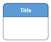 |
| StateWithInternalBehaviour | 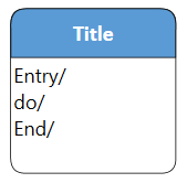 |
|
| CompositeState | 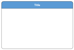 |
|
| Initial | |
|
| Final | |
|
| Choice |  |
|
| Note | |
|
| UMLRelationship | StrongEntity |  |
| Attribute | 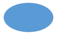 |
|
| MultivaluedAttribute |  |
|
| StrongRelationship |  |