Connector in WPF Diagram (SfDiagram)
17 Jun 202622 minutes to read
Connectors are objects used to create link between two points or nodes to indicate the flow of operation or relationships between them.

Connector types
Diagram supports to create five types of connectors. They are:
LineOrthogonalCubicBezierQuadraticBezierPolyLine
The DefaultConnectorType property allows you to change the connector type. By default, the diagram connector type is Orthogonal.
<!--Style for the Connector-->
<Style TargetType="syncfusion:Connector">
    <Setter Property="ConnectorGeometryStyle">
        <Setter.Value>
            <Style TargetType="Path">
                <Setter Property="Stroke" Value="#6BA5D7"/>
                <Setter Property="StrokeThickness" Value="1"/>
            </Style>
        </Setter.Value>
    </Setter>
    <Setter Property="TargetDecoratorStyle">
        <Setter.Value>
            <Style TargetType="Path">
                <Setter Property="Fill" Value="#6BA5D7"/>
                <Setter Property="StrokeThickness" Value="1"/>
            </Style>
        </Setter.Value>
    </Setter>
</Style>

<!--Initialize the Sfdiagram-->
<syncfusion:SfDiagram x:Name="diagram" DefaultConnectorType="Line">
    <syncfusion:SfDiagram.Connectors>
        <!--Initialize the Connector Collection-->
        <syncfusion:ConnectorCollection>
            <!--create the simple connector with source point and target point values-->
            <syncfusion:ConnectorViewModel x:Name="simpleConnector"
                                           SourcePoint="100,100"
                                           TargetPoint="200,200" />
        </syncfusion:ConnectorCollection>
    </syncfusion:SfDiagram.Connectors>
</syncfusion:SfDiagram>
//Initialize the SfDiagram
SfDiagram diagram = new SfDiagram();
//Define the Connector Type as line
diagram.DefaultConnectorType = ConnectorType.Line;
//creating simple connector through collction using source and target points.
ConnectorViewModel simpleConnector = new ConnectorViewModel()
{
SourcePoint = new Point(100,100),
TargetPoint = new Point(200,200),
};
//Adding the connector into Collection
(diagram.Connectors as ConnectorCollection).Add(simpleConnector);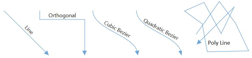
How to draw polyline
Polyline is a continuous line of a segment or a continuous line composed of more line segments. When you click the diagram page, a line will be drawn, and then new segments will be kept on added for every click on page. Line drawing will be stopped when double-click the page. This polyline will be drawn using the Tool, DrawingTool, and DefaultConnectorType properties.
<!--Initialize the Sfdiagram-->
<syncfusion:SfDiagram x:Name="diagram" DefaultConnectorType="PolyLine"
                      Tool="ContinuesDraw" DrawingTool="Connector" />
//Initialize the SfDiagram
SfDiagram diagram = new SfDiagram();
//Define the Connector type as poly line
diagram.DefaultConnectorType = ConnectorType.PolyLine;
//Define tool as continious draw and drawing tool as connector
diagram.Tool = Tool.ContinuesDraw;
diagram.DrawingTool = DrawingTool.Connector;
Free-hand drawing
Diagram has support for free-hand drawing to draw anything on the diagram page independently. Free-hand drawing will be enabled by using the DrawingTool property and setting its value to FreeHand.
<!--Initialize the Sfdiagram-->
<syncfusion:SfDiagram x:Name="diagram" Tool="ContinuesDraw" DrawingTool="FreeHand" />
//Initialize the SfDiagram
SfDiagram diagram = new SfDiagram();
diagram.Tool = Tool.ContinuesDraw;
//Define drawing tool as free hand
diagram.DrawingTool = DrawingTool.FreeHand;
For more information about changing drawing tool of diagram, refer to Tools.
Find the Drawing tools sample to depict the Tools.
Create connector
Connector can be created by defining the start and end points. The path to be drawn can be defined with a collection of Segments.
Create connectors through connection points
The connector can be created by defining the source and target point of the connection. The SourcePoint and TargetPoint properties, which are Point type allows you to set or get the start and end points of a connection.
<!--Initialize the Sfdiagram-->
<syncfusion:SfDiagram x:Name="diagram" DefaultConnectorType="Line">
    <syncfusion:SfDiagram.Connectors>
        <!--Initialize the Connector Collection-->
        <syncfusion:ConnectorCollection>
            <!--create the simple connector with source point and target point values-->
            <syncfusion:ConnectorViewModel x:Name="simpleConnector"
                                           SourcePoint="100,100" TargetPoint="200,200" />
        </syncfusion:ConnectorCollection>
    </syncfusion:SfDiagram.Connectors>
</syncfusion:SfDiagram>
//Initialize the SfDiagram
SfDiagram diagram = new SfDiagram();
//Define the Connector Type
diagram.DefaultConnectorType = ConnectorType.Line;
//creating simple connector through collection using source and target points.
ConnectorViewModel simpleConnector = new ConnectorViewModel()
{
SourcePoint = new Point(100,100),
TargetPoint = new Point(200,200),
};
//Adding the connector into Collection
(diagram.Connectors as ConnectorCollection).Add(simpleConnector);
Create connection between nodes
The connector can be created between nodes to display the relationship between them. The SourceNode/SourceNodeID and TargetNode/TargetNodeID properties allows you to represent the nodes to be connected.
<!--Initialize the Sfdiagram-->
<syncfusion:SfDiagram x:Name="diagram">
    <syncfusion:SfDiagram.Nodes>
        <!--Initialize the Nodes Collection-->
        <syncfusion:NodeCollection>
            <!--Creating source node-->
            <syncfusion:NodeViewModel ID="sourceNode"
                                      UnitWidth="100" UnitHeight="50"
                                      OffsetX="300" OffsetY="200"
                                      Shape="{StaticResource Rectangle}"/>
            <!--Creating target node-->
            <syncfusion:NodeViewModel ID="targetNode"
                                      UnitWidth="100" UnitHeight="50"
                                      OffsetX="500" OffsetY="200"
                                      Shape="{StaticResource Rectangle}"/>
        </syncfusion:NodeCollection>
    </syncfusion:SfDiagram.Nodes>

    <syncfusion:SfDiagram.Connectors>
        <!--Initialize the ConnectorCollection-->
        <syncfusion:ConnectorCollection>
            <!--create the connector with source node and target node values-->
            <syncfusion:ConnectorViewModel x:Name="NodeToNodeConnection"
                                           SourceNodeID="sourceNode"
                                           TargetNodeID="targetNode"/>
        </syncfusion:ConnectorCollection>
    </syncfusion:SfDiagram.Connectors>
</syncfusion:SfDiagram>
//Initialize the SfDiagram
SfDiagram diagram = new SfDiagram();
//creating source node
NodeViewModel sourcenode = new NodeViewModel()
{
UnitWidth = 100,
UnitHeight = 50,
OffsetX = 300,
OffsetY = 200,
Shape = this.Resources["Rectangle"],
};
//creating target node
NodeViewModel targetenode = new NodeViewModel()
{
UnitWidth = 100,
UnitHeight = 50,
OffsetX = 500,
OffsetY = 200,
Shape = this.Resources["Rectangle"],
};
//Adding nodes into Collection
(diagram.Nodes as NodeCollection).Add(sourcenode);
(diagram.Nodes as NodeCollection).Add(targetenode);
//create the connector with source node and target node values
ConnectorViewModel nodeToNodeConnection = new ConnectorViewModel()
{
SourceNode = sourcenode,
TargetNode = targetenode,
};
//Adding connector into Collection
(diagram.Connectors as ConnectorCollection).Add(nodeToNodeConnection);
Connections with ports
By default, connections are created at the intersecting point of segments and node bounds. The connection between any specific point of source and target nodes can be achieved with ports.
The SourcePort/SourcePortID and TargetPort/TargetPortID properties allows you to create connections between some specific points of Source/Target nodes.
<!--Initialize the Sfdiagram-->
<syncfusion:SfDiagram x:Name="diagram">
    <syncfusion:SfDiagram.Nodes>
        <!--Initialize the Nodes Collection-->
        <syncfusion:NodeCollection>
            <!--Creating source node-->
            <syncfusion:NodeViewModel ID="sourceNode"
                                      UnitWidth="100" UnitHeight="50"
                                      OffsetX="300" OffsetY="200"
                                      Shape="{StaticResource Rectangle}">
                <syncfusion:NodeViewModel.Ports>
                    <!--Initialize the Ports Collection-->
                    <syncfusion:PortCollection>
                        <!--create source node port-->
                        <syncfusion:NodePortViewModel ID="SourcePort"
                                                      NodeOffsetX="0"
                                                      NodeOffsetY="0.5"/>
                    </syncfusion:PortCollection>
                </syncfusion:NodeViewModel.Ports>
            </syncfusion:NodeViewModel>

            <!--Creating target node-->
            <syncfusion:NodeViewModel ID="targetNode"
                                      UnitWidth="100" UnitHeight="50"
                                      OffsetX="500" OffsetY="200"
                                      Shape="{StaticResource Rectangle}">
                <syncfusion:NodeViewModel.Ports>
                    <!--Initialize the Ports Collection-->
                    <syncfusion:PortCollection>
                        <!--create source node port-->
                        <syncfusion:NodePortViewModel ID="TargetPort"
                                                      NodeOffsetX="1"
                                                      NodeOffsetY="0.5"/>
                    </syncfusion:PortCollection>
                </syncfusion:NodeViewModel.Ports>
            </syncfusion:NodeViewModel>
        </syncfusion:NodeCollection>
    </syncfusion:SfDiagram.Nodes>

    <syncfusion:SfDiagram.Connectors>
        <!--Initialize the ConnectorCollection-->
        <syncfusion:ConnectorCollection>
            <!--create the connector with source node and target node values-->
            <syncfusion:ConnectorViewModel x:Name="PortToPortConnection"
                                           SourcePortID="SourcePort"
                                           TargetPortID="TargetPort"
                                           SourceNodeID="sourceNode"
                                           TargetNodeID="targetNode"/>
        </syncfusion:ConnectorCollection>
    </syncfusion:SfDiagram.Connectors>
</syncfusion:SfDiagram>
//Initialize the SfDiagram
SfDiagram diagram = new SfDiagram();
//Create source node port
NodePortViewModel sourcePort = new NodePortViewModel()
{
NodeOffsetX = 0,
NodeOffsetY = 0.5,
};
//Create target node port
NodePortViewModel targetPort = new NodePortViewModel()
{
NodeOffsetX = 1,
NodeOffsetY = 0.5,
};
//creating source node
NodeViewModel sourcenode = new NodeViewModel()
{
UnitWidth = 100,
UnitHeight = 50,
OffsetX = 300,
OffsetY = 200,
Shape = this.Resources["Rectangle"],
Ports = new PortCollection()
{
//Add source port to source node
sourcePort,
}
};
//creating target node
NodeViewModel targetenode = new NodeViewModel()
{
UnitWidth = 100,
UnitHeight = 50,
OffsetX = 500,
OffsetY = 200,
Shape = this.Resources["Rectangle"],
Ports = new PortCollection()
{
//Add target port to target node
targetPort,
}
};
//Adding nodes into Collection
(diagram.Nodes as NodeCollection).Add(sourcenode);
(diagram.Nodes as NodeCollection).Add(targetenode);
//create the connector from port to port
ConnectorViewModel PortToPortConnection = new ConnectorViewModel()
{
SourceNode = sourcenode,
//Define the source port
SourcePort = sourcePort,
TargetNode = targetenode,
//Define the target port
TargetPort = targetPort,
};
//Adding port to port connector into connector Collection
(diagram.Connectors as ConnectorCollection).Add(PortToPortConnection);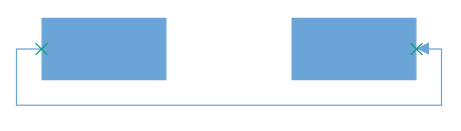
For more details about Ports, refer to Port.
Find the Connector creation sample to depict the connector creation.
Draw connectors
Connectors can be interactively drawn by clicking and dragging on the diagram surface by using the drawing tool. For more information about drawing connectors, refer to Drawing Tools.
Connectors through data source
Connectors are automatically generated based on the relationships defined through the data source. For more information about data source, refer to DataSource.
Add connectors from stencil
Connectors can be predefined and added to the stencil. You can drop those connectors into the diagram, when required.
For more information about adding connectors from stencil, refer to Stencil.
See Also
How to apply built-in theme for node and connector?
How to decide whether to drag or draw a connection on port at runtime?
How to customize the context menu?
How to create port at runtime though SetTool?
How to customize the connection indicator style of node and port?
How to restrict annotation editing by double-clicking the node or connector?
How to disable the animation while creating a connection in diagram?
How to bring the specific diagram object to the center or viewport of the Diagram?
How to show the copied diagram elements as preview image along with the mouse pointer?
How to restrict Connector’s source/target changing from native Nodes to other Nodes?
How to restrict diagram objects dragging in the positive side?
How to use the property grid for diagram elements?
How to override the default cursors while interact on diagram objects?
How to create parent and child relationship by drag and drop nodes?
How to get or set the positions of the segments by programmatically?
How to toggle the visibility of connector at runtime?
How to detect or get notification when editing the thumbs of connector?
How to Notify when diagramming object is duplicated with source?
How to programmatically Show/Hide the Annotations of node and connector?
How to customize the bridging style for connector?
How to add port to the connector?
How to customize the direction of bridge?
How to add space between connector decorator and node?
How to disable the selection of diagram objects?
How to Obtain the Polyline Connector Completed status in WPF Diagram?
How to Obtain InConnectors and OutConnectors of Node in WPF Diagram?
How to Fit Selected Nodes and Connectors to the WPF Diagram Window?
How to Get the Node or Connector in the MouseMove Event in the WPF Diagram (SfDiagram)?
How to update the same length for connector segments in the WPF Diagram (SfDiagram)?
How to manage the visibility of node and connector objects in the WPF Diagram (SfDiagram)?
How to change the connector style based on its SourcePort style in WPF Diagram (SfDiagram)?
How to identify the dragging state of connectors in the WPF Diagram (SfDiagram)?
NOTE
Looking for the full WPF Diagram component overview, features, pricing, and documentation? Visit the WPF Diagram page.