Flowchart Layout in WPF Diagram
18 Nov 201824 minutes to read
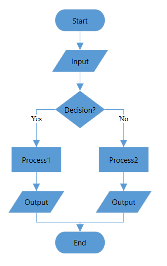
The flowchart layout is a diagrammatic representation of a process, workflow, system, or computer algorithm. Flowcharts use various kinds of symbols to illustrate the different types of actions, and the symbols are connected together with arrows showing the flow direction of a process.
Common flowchart symbols
Different flowchart symbols have different meanings that are used to represent different states in a flowchart. The following table describes the most common flowchart symbols that are used to create a flowchart.
| Symbol | Built-in resource key in SfDiagram | Description |
|---|---|---|
 |
Terminator/StartOrEnd | Indicates the beginning and ending of the process. |
 |
Data | Indicates data input or output for a process. |
 |
Process | Represents an operation or set of operations and data manipulations. |
 |
Decision | Shows a branching point where the decision is made to choose one of the two paths. |
 |
Document | Represents a single document or report in the process. |
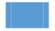 |
SubProcess / PredefinedProcess | Represents a sequence of actions that combine to perform a specific task that is defined elsewhere. Both keys (SubProcess and PredefinedProcess) map to the same shape; use either name when binding via ShapeMapping. |
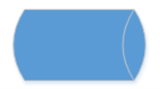 |
DirectData | Represents a collection of information that allows searching, sorting, and filtering. Use for read/write data sources such as databases or files. |
 |
StoredData | Represents a step where data is stored within a process. Use for persistent storage (for example, disk or tape). |
 |
ManualInput | Represents the manual input of data into a field or step in a process. Use when the value is keyed in by a user. (File renamed to …-symbol.png to match the other entries.) |
 |
ManualOperation | Represents an operation in a process that must be done manually, not automatically. |
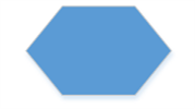 |
Preparation | Represents a setup or initialization process to another step in the process. |
 |
OnPageReference | Represents a pair of labeled connectors used to link long or confusing lines on a flowchart. |
 |
OffPageReference | Represents a labeled connector used to link two flowcharts on different pages. |
 |
MultiDocument | Represents multiple documents or reports in the process. |
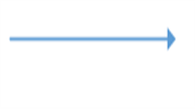 |
Represents a direction of flow from one step to another. It will get created automatically based on the relationship between the parent and child. |
We have provided some more built-in Shapes as ResourceDictionary. For more Shapes, refer to this page.
<Window.Resources>
    <ResourceDictionary>
        <ResourceDictionary.MergedDictionaries>
            <!--Initialize Shapes-->
            <ResourceDictionary Source="/Syncfusion.SfDiagram.Wpf;component/Resources/BasicShapes.xaml"/>
        </ResourceDictionary.MergedDictionaries>
    </ResourceDictionary>
</Window.Resources>

<local:DataItems x:Key="Dataitems">
<local:ItemInfo Id="1" NodeShape="{StaticResource Terminator}" Width="80" Height="35" Name="Start"/>
<local:ItemInfo Id="2" NodeShape="{StaticResource Data}" Width="90" Height="35" Name="Input">
    <local:ItemInfo.ParentId>
        <local:LabelList>
            <sys:String>1</sys:String>
        </local:LabelList>
    </local:ItemInfo.ParentId>
</local:ItemInfo>
<local:ItemInfo Id="3" NodeShape="{StaticResource Decision}" Width="80" Height="60" Name="Decision?">
    <local:ItemInfo.ParentId>
        <local:LabelList>
            <sys:String>2</sys:String>
        </local:LabelList>
    </local:ItemInfo.ParentId>
</local:ItemInfo>
<local:ItemInfo Id="4" NodeShape="{StaticResource Process}" Width="80" Height="40" Name="Process1">
    <local:ItemInfo.ParentId>
        <local:LabelList>
            <sys:String>3</sys:String>
        </local:LabelList>
    </local:ItemInfo.ParentId>
    <local:ItemInfo.Label>
        <local:LabelList>
                <sys:String>Yes</sys:String>
        </local:LabelList>
    </local:ItemInfo.Label>
</local:ItemInfo>
<local:ItemInfo Id="5" NodeShape="{StaticResource Process}" Width="80" Height="40" Name="Process2">
    <local:ItemInfo.ParentId>
        <local:LabelList>
            <sys:String>3</sys:String>
        </local:LabelList>
    </local:ItemInfo.ParentId>
    <local:ItemInfo.Label>
        <local:LabelList>
            <sys:String>No</sys:String>
        </local:LabelList>
    </local:ItemInfo.Label>
</local:ItemInfo>
<local:ItemInfo Id="6" NodeShape="{StaticResource Data}" Width="90" Height="35" Name="Output">
    <local:ItemInfo.ParentId>
        <local:LabelList>
            <sys:String>5</sys:String>
        </local:LabelList>
    </local:ItemInfo.ParentId>
</local:ItemInfo>
<!--Note: Id=6 and Id=7 share the same Name="Output". Only the Id must be unique;
    Name is for display purposes and is allowed to repeat. The DataSourceSettings
    keying uses Id, not Name.-->
<local:ItemInfo Id="7" NodeShape="{StaticResource Data}" Width="90" Height="35" Name="Output">
    <local:ItemInfo.ParentId>
        <local:LabelList>
            <sys:String>4</sys:String>
        </local:LabelList>
    </local:ItemInfo.ParentId>
</local:ItemInfo>
<local:ItemInfo Id="8" NodeShape="{StaticResource Terminator}" Width="80" Height="35" Name="End">
    <local:ItemInfo.ParentId>
        <local:LabelList>
            <sys:String>6</sys:String>
            <sys:String>7</sys:String>
        </local:LabelList>
    </local:ItemInfo.ParentId>
</local:ItemInfo>
</local:DataItems>
<!--Initializes the Layout-->
<syncfusion:FlowchartLayout x:Key="Layout" Orientation="LeftToRight"
                            HorizontalSpacing="50" VerticalSpacing="30"
                            YesBranchDirection="LeftInFlow"
                            NoBranchDirection="RightInFlow">
</syncfusion:FlowchartLayout>

<!--Initializes the LayoutManager-->
<syncfusion:LayoutManager x:Key="layoutmanager" Layout="{StaticResource Layout}"/>

<!--Initializes the DataSourceSettings -->
<syncfusion:FlowchartDataSourceSettings x:Key="DataSourceSettings"
                                        DataSource="{StaticResource Dataitems}"
                                        ParentId="ParentId" Id="Id"
                                        ShapeMapping="NodeShape"
                                        WidthMapping="Width"
                                        HeightMapping="Height"
                                        ConnectorTextMapping="Label"
                                        ContentMapping="Name"/>

<!--Initializes the SfDiagram -->
<syncfusion:SfDiagram x:Name="diagram" Grid.Column="0"
                      LayoutManager="{StaticResource layoutmanager}"
                      DataSourceSettings="{StaticResource DataSourceSettings}">
    <syncfusion:SfDiagram.Theme>
        <syncfusion:OfficeTheme/>
    </syncfusion:SfDiagram.Theme>
</syncfusion:SfDiagram>
//Initialize Diagram
SfDiagram diagram = new SfDiagram();
//Initialize Node Collection
diagram.Nodes = new ObservableCollection<NodeViewModel>();
//Initialize Connector Collection
diagram.Connectors = new ObservableCollection<ConnectorViewModel>();
//ItemInfo must expose a public parameterless constructor so that
//FlowchartDataSourceSettings can instantiate it from the DataSource
//collection. The class below demonstrates the required shape.
//Subscribe to ItemAdded
(diagram.Info as IGraphInfo).ItemAdded += MainWindow_ItemAdded;
//Handler for ItemAdded (placeholder: customize per requirements)
private void MainWindow_ItemAdded(object sender, ItemAddedEventArgs args)
{
//Perform any per-item initialization here.
}
//Initialize DataSourceSettings for Diagram
diagram.DataSourceSettings = new FlowchartDataSourceSettings()
{
ParentId = "ParentId",
Id = "Id",
DataSource = GetData(),
ConnectorTextMapping = "Label",
ContentMapping = "Name",
ShapeMapping = "NodeShape",
WidthMapping = "Width",
HeightMapping = "Height"
};
//Initialize LayoutManager
LayoutManager layoutManager = new LayoutManager();
//Initialize Layout for Diagram
layoutManager.Layout = new FlowchartLayout()
{
Orientation = FlowchartOrientation.TopToBottom,
YesBranchDirection = BranchDirection.LeftInFlow,
NoBranchDirection = BranchDirection.RightInFlow,
HorizontalSpacing = 50,
VerticalSpacing = 30
};
//Initialize theming style for Diagram
diagram.Theme = new OfficeTheme();
//Assign the LayoutManager to the diagram (do not re-initialize the manager here).
diagram.LayoutManager = layoutManager;
//Add the Diagram as a child of the main window grid.
WindowGrid.Children.Add(diagram);
//Initializes the DataSource collection
private DataItems GetData()
{
DataItems itemscollection = new DataItems();
itemscollection.Add(new ItemInfo()
{
Id ="1",
NodeShape =App.Current.Resources["Terminator"] as string,
Name = "Start",
Height =35,
Width =80
});
itemscollection.Add(new ItemInfo()
{
Id = "2",
ParentId =new List<string> { "1" },
NodeShape = App.Current.Resources["Data"] as string,
Name = "Input",
Height = 35,
Width =90
});
itemscollection.Add(new ItemInfo()
{
Id = "3", ParentId =new List<string> { "2" },
NodeShape = App.Current.Resources["Decision"] as string,
Name = "Decision?",
Height =60,
Width = 80
});
itemscollection.Add(new ItemInfo()
{
Id = "4",
ParentId = new List<string> { "3" },
Label =new List<string> {"Yes" },
NodeShape = App.Current.Resources["Process"] as string,
Name = "Process1",
Height = 40,
Width = 80
});
itemscollection.Add(new ItemInfo()
{
Id = "5",
ParentId = new List<string> { "3" },
Label = new List<string> { "No" },
NodeShape = App.Current.Resources["Process"] as string,
Name = "Process2",
Height = 40,
Width = 80
});
itemscollection.Add(new ItemInfo()
{
Id = "6",
ParentId = new List<string> { "5" },
NodeShape = App.Current.Resources["Data"] as string,
Name = "Output",
Height = 35,
Width = 90
});
itemscollection.Add(new ItemInfo()
{
Id = "7",
ParentId = new List<string> { "4" },
NodeShape = App.Current.Resources["Data"] as string,
Name = "Output",
Height = 35,
Width = 90
});
itemscollection.Add(new ItemInfo()
{
Id = "8",
ParentId = new List<string> { "6","7" },
NodeShape =App.Current.Resources["Terminator"] as string,
Name = "End",
Height = 35,
Width = 80
});
return itemscollection;
}
//Data Object Class.
//A parameterless constructor is required when ItemInfo instances are
//created via XAML property syntax or by the FlowchartDataSourceSettings.
public class ItemInfo
{
public ItemInfo()
{
}
public string Name { get; set; }
public string Id { get; set; }
public List<string> ParentId { get; set; }
public string NodeShape { get; set; }
public List<string> Label { get; set; }
public double Width { get; set; }
public double Height { get; set; }
}
//Collection to hold the Data Object class
public class DataItems : ObservableCollection<ItemInfo>
{
}
Customize flowchart layout orientation
The flow direction of nodes can be customized using the flowchart orientation, either vertically from top to bottom or horizontally from left to right. The Orientation property of the FlowchartLayout class allows you to define the flow direction for a flowchart.
The FlowchartOrientation enum has the following values:
| Value | Description |
|---|---|
TopToBottom |
Defines the flow orientation as top to bottom. The default value. |
LeftToRight |
Defines the flow orientation as left to right. |
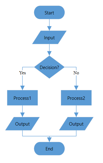
TopToBottom orientation
Arranges the element in the layout vertically from top to bottom.
<syncfusion:FlowchartLayout x:Key="Layout" Orientation="TopToBottom"/>//Initialize LayoutManager
LayoutManager layoutManager = new LayoutManager();
//Initialize Layout for Diagram
layoutManager.Layout = new FlowchartLayout()
{
Orientation = FlowchartOrientation.TopToBottom,
};
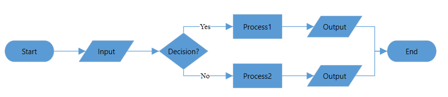
LeftToRight orientation
Arranges the element in the layout horizontally from left to right.
<syncfusion:FlowchartLayout x:Key="Layout" Orientation="LeftToRight"/>//Initialize LayoutManager
LayoutManager layoutManager = new LayoutManager();
//Initialize Layout for Diagram
layoutManager.Layout = new FlowchartLayout()
{
Orientation = FlowchartOrientation.LeftToRight,
};
Customize the decision output directions
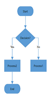
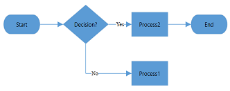
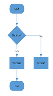
The decision symbol denotes a question that can be answered in binary format (Yes/No, True/False). The output direction of the decision symbol can be controlled by the direction of the “Yes” and “No” branches using the YesBranchDirection and NoBranchDirection properties of the FlowchartLayout class.
The supported BranchDirection enum values are:
| Value | Description |
|---|---|
LeftInFlow |
Arranges the Yes/No branch to the left of the decision symbol. |
RightInFlow |
Arranges the Yes/No branch to the right of the decision symbol. |
SameAsFlow |
Arranges the Yes/No branch in the same direction as the flow of the decision symbol. |
The following table illustrates the behavior:
YesBranchDirection |
NoBranchDirection |
TopToBottom |
LeftToRight |
|---|---|---|---|
LeftInFlow |
RightInFlow |
 |
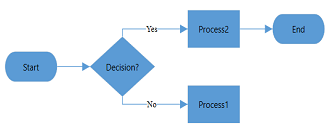 |
RightInFlow |
LeftInFlow |
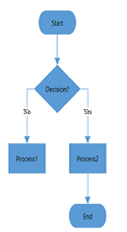 |
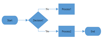 |
SameAsFlow |
RightInFlow |
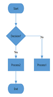 |
 |
SameAsFlow |
SameAsFlow |
 |
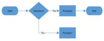 |
If both branch directions are the same, the Yes branch is prioritized.
Custom Yes and No branch values
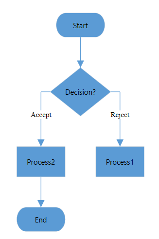
The decision symbol produces two output branches: a Yes branch and a No branch. If the connector text of an output branch matches a value in the YesBranchValues property of the FlowchartLayout class, it is considered the Yes branch. Similarly, if the connector text matches a value in the NoBranchValues property, it is considered the No branch.
By default, YesBranchValues contains Yes and True; NoBranchValues contains No and False. Any text value can be assigned to a connector to describe the flow, and any string value can be added to YesBranchValues and NoBranchValues. To decide the flow as if/else, the connector text must match a value in YesBranchValues or NoBranchValues. If a connector text matches neither, it falls back to the first matching branch in declaration order.
<syncfusion:FlowchartLayout x:Key="Layout" Orientation="TopToBottom"
                            YesBranchDirection="LeftInFlow"
                            NoBranchDirection="RightInFlow"
                            HorizontalSpacing="50"
                            VerticalSpacing="30">
    <syncfusion:FlowchartLayout.YesBranchValues>
        <local:LabelList>
            <sys:String>Accept</sys:String>
            <sys:String>Yes</sys:String>
        </local:LabelList>
    </syncfusion:FlowchartLayout.YesBranchValues>
    <syncfusion:FlowchartLayout.NoBranchValues>
        <local:LabelList>
            <sys:String>Reject</sys:String>
            <sys:String>No</sys:String>
        </local:LabelList>
    </syncfusion:FlowchartLayout.NoBranchValues>
</syncfusion:FlowchartLayout>
//Initialize LayoutManager
LayoutManager layoutManager = new LayoutManager();
//Initialize Layout for Diagram
layoutManager.Layout = new FlowchartLayout()
{
Orientation = FlowchartOrientation.TopToBottom,
YesBranchDirection = BranchDirection.LeftInFlow,
NoBranchDirection = BranchDirection.RightInFlow,
YesBranchValues=new List<string> { "Accept","Yes"},
NoBranchValues=new List<string> { "Reject","No"},
HorizontalSpacing = 50,
VerticalSpacing = 30
};
Customize vertical and horizontal spacing
Control the spacing between the nodes, both horizontally and vertically, using the HorizontalSpacing and VerticalSpacing properties of the FlowchartLayout class.
<syncfusion:FlowchartLayout x:Key="Layout" HorizontalSpacing="50" VerticalSpacing="30"/>//Initialize LayoutManager
LayoutManager layoutManager = new LayoutManager();
//Initialize Layout for Diagram
layoutManager.Layout = new FlowchartLayout()
{
HorizontalSpacing = 50,
VerticalSpacing = 30
};