Connector in UWP Diagram (SfDiagram)
16 Dec 202416 minutes to read
Connectors are objects used to create link between two Points, Nodes or ports to represent the relationships between them.
Define Connector
Connector can be created by defining the start and end points. The Path to be drawn can be defined with a collection of segments. The SourcePoint and TargetPoint properties of Connector allow you to define the end points of a Connector.
<!--Style for the Connector-->
<Style TargetType="syncfusion:Connector">
  <Setter Property="ConnectorGeometryStyle">
    <Setter.Value>
      <Style TargetType="Path">
        <Setter Property="Stroke" Value="CornflowerBlue"></Setter>
        <Setter Property="StrokeThickness" Value="1"></Setter>
      </Style>
    </Setter.Value>
  </Setter>
  <Setter Property="TargetDecoratorStyle">
    <Setter.Value>
      <Style TargetType="Path">
        <Setter Property="Fill" Value="CornflowerBlue"></Setter>
        <Setter Property="StrokeThickness" Value="1"></Setter>
      </Style>
    </Setter.Value>
  </Setter>
</Style>

<!--Initialize the Sfdiagram-->
<syncfusion:SfDiagram x:Name="diagram" DefaultConnectorType="Line">
  <syncfusion:SfDiagram.Connectors>
  <!--Initialize the ConnectorCollection-->
    <syncfusion:ConnectorCollection>
    <!--Initialize the Connector-->
      <syncfusion:ConnectorViewModel SourcePoint="100,100" TargetPoint="200,200">
      </syncfusion:ConnectorViewModel>
    </syncfusion:ConnectorCollection>
  </syncfusion:SfDiagram.Connectors>
</syncfusion:SfDiagram>
//Define the ConnectorType
diagram.DefaultConnectorType = ConnectorType.Line;
//Define the ConnectorCollection
diagram.Connectors = new ConnectorCollection();
//Define the Connector
ConnectorViewModel connector = new ConnectorViewModel()
{
//Define the Source and TargetPoint
SourcePoint = new Point(100, 100),
TargetPoint = new Point(200, 200),
};
//Adding Connector to Collection
(diagram.Connectors as ConnectorCollection).Add(connector);Connectors from stencil
Connectors can be predefined and added to the stencil. You can drop those Connectors into the Diagram, when required.
For more information about adding Connectors from stencil, refer to Stencil.
Connectors through data source
Connectors are automatically generated based on the relationships defined through the data source. For more information about data source, refer to Data Source.
Draw Connectors
Connectors can be interactively drawn by clicking and dragging on the Diagram surface by using Drawing Tool. For more information about drawing Connectors, refer to Draw Connectors.
Connect Nodes
The SourceNode and TargetNode properties allow to define the Nodes to be connected.
//Define the NodeCollection
diagram.Nodes = new NodeCollection();
//Defining the Node
NodeViewModel node1 = AddNode(100,"Node1");
NodeViewModel node2 = AddNode(250,"Node2");
//Adding Node to Collection
(diagram.Nodes as NodeCollection).Add(node1);
(diagram.Nodes as NodeCollection).Add(node2);
//Define the ConnectorCollection
diagram.Connectors = new ConnectorCollection();
//Define the Connector
ConnectorViewModel connector1 = new ConnectorViewModel()
{
    SourceNode=node1,
    TargetNode=node2,
    ConnectorGeometryStyle = this.Resources["ConnectorStyle"] as Style,
};
//Adding Connector to Collection
(diagram.Connectors as ConnectorCollection).Add(connector1);


//Creating NodeViewModel
public NodeViewModel AddNode(double offsetX, string text)
{
    NodeViewModel node = new NodeViewModel();
    node.UnitHeight = 60;
    node.UnitWidth = 100;
    node.OffsetX = offsetX;
    node.OffsetY = 100;
    node.Shape = new RectangleGeometry { Rect = new Rect(0, 0, 10, 10) };
    return node;
}
The SourceNodeID and TargetNodeID properties also allows to define the nodes to be connected.
NOTE
By default, connections are created at the intersecting point of Segments and Node bounds. The connection between any specific point of Source and Target Nodes can be achieved with Ports.
Connections with Ports
The SourcePort/SourcePortID and TargetPort/TargetPortID properties allow to create connections between some specific points of Source/Target Nodes.
For Connections with Ports, please refer to Port.
Segments
The path of the Connector is defined with a collection of Segments.
Straight
Straight segment allows to create a straight line. To create a straight line, you should specify the segment as StraightSegment and add a straight segment to collection.
//Define the ConnectorCollection
diagram.Connectors = new ConnectorCollection();
//Define the Connector
ConnectorViewModel connector = new ConnectorViewModel()
{
    SourcePoint = new Point(100, 100),
    TargetPoint = new Point(200, 200),
    //Define the SegmentCollection
    Segments = new ObservableCollection<IConnectorSegment>()
    {
        new StraightSegment()
    }
};
//Adding Connector to Collection
(diagram.Connectors as ConnectorCollection).Add(connector);
Orthogonal
Orthogonal segments are used to create segments that are perpendicular to each other. Set the segment as OrthogonalSegment to create the default orthogonal segment.
//Define the ConnectorCollection
diagram.Connectors = new ConnectorCollection();
//Define the Connector
ConnectorViewModel connector = new ConnectorViewModel()
{
    SourcePoint = new Point(100, 100),
    TargetPoint = new Point(200, 200),
    //Define the SegmentCollection
    Segments = new ObservableCollection<IConnectorSegment>()
    {
        new OrthogonalSegment()
    }
};
//Adding Connector to CollectionS
(diagram.Connectors as ConnectorCollection).Add(connector);
CubicCurveSegment
Cubic curve segments are used to create curve segments and the curves are configurable with the control points.To create a Curve line, you should specify the segment as CubicCurveSegment and add a CubicCurveSegment to collection.
//Adding Connector to Collection
(diagram.Connectors as ConnectorCollection).Add(connector);
//Define the ConnectorCollection
diagram.Connectors = new ConnectorCollection();
//Define the Connector
ConnectorViewModel connector = new ConnectorViewModel()
{
    SourcePoint = new Point(100, 100),
    TargetPoint = new Point(200, 200),
    //Define the SegmentCollection
    Segments = new ObservableCollection<IConnectorSegment>()
    {
        new CubicCurveSegment()
    }
};
//Adding Connector to Collection
(diagram.Connectors as ConnectorCollection).Add(connector);
Avoid overlapping
Orthogonal segments are automatically re-routed, in order to avoid overlapping with the source and target Nodes.
NOTE
Overlapping with Source and Target nodes are only avoided. Other nodes are not considered as obstacles.
Decorator
Start and end points of a Connector can be decorated with some customizable shapes like arrows, circles, diamond or path. You can decorate the connection end points with the SourceDecorator and TargetDecorator properties of Connector.
The SourceDecoratorStyle and TargetDecoratorStyle properties allows to define the shape of the decorators.
The SourceDecoratorPivot and TargetDecoratorPivot properties allows to Customize the position of the decorators in the connector.
SegmentDecorators
SegmentDecorator property allows to customize the shape within the Connector. SegmentDecoratorStyle property allows to customize the Style of SegmentDecorator.
//Define the collection of SegmentDecorator
SegmentDecorators = new ObservableCollection<ISegmentDecorator>()
{
    //Define the SegmentDecorator
    new SegmentDecorator()
    {
        //Define the Shape of SegmentDecorator
        Shape = "M0,0 L10,5 L0,10",
        Length =0.4
    }
}
Corner radius
Corner radius allows to create Connectors with rounded corners. The radius of the rounded corner is set with CornerRadius property.
<!--Initialize the Sfdiagram-->
<syncfusion:SfDiagram x:Name="diagram">
  <syncfusion:SfDiagram.Connectors>
    <syncfusion:ConnectorCollection>
      <!--Initialize the Connector-->
      <syncfusion:ConnectorViewModel SourcePoint="100,100" TargetPoint="200,200" CornerRadius="10">
      </syncfusion:ConnectorViewModel>
    </syncfusion:ConnectorCollection>
  </syncfusion:SfDiagram.Connectors>
</syncfusion:SfDiagram>
//Define the ConnectorCollection
diagram.Connectors = new ConnectorCollection();
//Define the Connector
ConnectorViewModel connector1 = new ConnectorViewModel()
{
//Define the CornerRadius
CornerRadius = 10,
SourcePoint = new Point(100, 100),
TargetPoint = new Point(200, 200),
};
//Adding Connector to Collection
(diagram.Connectors as ConnectorCollection).Add(connector1);Padding
Padding is used to leave space between the Connector’s end point and the object to where it is connected. The SourcePadding and TargetPadding properties of Connector define the space to be left between the connection end points and the source and target Nodes of Connector.
//Define the ConnectorCollection
diagram.Connectors = new ConnectorCollection();
//Define the Connector
ConnectorViewModel connector1 = new ConnectorViewModel()
{
    SourceNode=node1,
    TargetNode=node2,
    //Space between SourceNode and SourceObject
    SourcePadding=5,
    //Space between TargetNode and TargetObject
    TargetPadding = 5,
    ConnectorGeometryStyle = this.Resources["ConnectorStyle"] as Style,
};
//Adding Connector to Collection
(diagram.Connectors as ConnectorCollection).Add(connector1);
Bridging
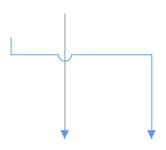
Line Bridging creates a bridge for lines to smartly cross over other lines, at points of interaction. When two lines Connectors meet each other, the line with higher z-order (upper one) draws an arc over the underlying Connector. Bridging can be enabled/disabled either with the Constraints property of Connector or with GraphConstraints.
The Direction of Bridge can be customized with property BridgeDirection.
<Grid>
  <!--Initialize the SfDiagram with Constraints and BridgeDirection-->
  <syncfusion:SfDiagram x:Name="diagram" BridgeDirection="Bottom" Constraints="Bridging">
    <syncfusion:SfDiagram.Connectors>
      <!--Initialize the ConnectorCollection-->
      <syncfusion:ConnectorCollection>
        <!--Initialize the Connector-->
        <syncfusion:ConnectorViewModel SourcePoint="88,183" TargetPoint="250,300">
        </syncfusion:ConnectorViewModel>
        <syncfusion:ConnectorViewModel SourcePoint="150,156" TargetPoint="150,300">
        </syncfusion:ConnectorViewModel>
      </syncfusion:ConnectorCollection>
    </syncfusion:SfDiagram.Connectors>
  </syncfusion:SfDiagram>
</Grid>
//Define the BridgeDirection
diagram.BridgeDirection = BridgeDirection.Bottom;
//Define Constraints
diagram.Constraints = diagram.Constraints | GraphConstraints.Bridging;
//Define the ConnectorCollection
diagram.Connectors = new ConnectorCollection();
//Define the Connector
ConnectorViewModel connector = new ConnectorViewModel()
{
SourcePoint = new Point(88, 183),
TargetPoint = new Point(250, 300)
};
//Adding Connector to Collection
(diagram.Connectors as ConnectorCollection).Add(connector);
ConnectorViewModel connector1 = new ConnectorViewModel()
{
SourcePoint = new Point(150, 156),
TargetPoint = new Point(150, 300),
};
(diagram.Connectors as ConnectorCollection).Add(connector1);
NOTE
Bezier segments do not support Bridging.
BridgeSpace
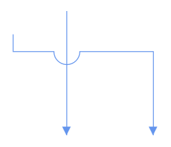
The BridgeSpace property allows to customize the size of bridge in a connector.
//Define the BridgeDirection
diagram.BridgeDirection = BridgeDirection.Bottom;
//Define Constraints
diagram.Constraints = diagram.Constraints | GraphConstraints.Bridging;
//Define the ConnectorCollection
diagram.Connectors = new ConnectorCollection();
//Define the Connector
ConnectorViewModel connector = new ConnectorViewModel()
{
    //Define the Bridge space of the connector
    BridgeSpace=30,
    SourcePoint = new Point(88, 183),
    TargetPoint = new Point(250, 300),
};
//Adding Connector to Collection
(diagram.Connectors as ConnectorCollection).Add(connector);
ConnectorViewModel connector1 = new ConnectorViewModel()
{
    SourcePoint = new Point(150, 156),
    TargetPoint = new Point(150, 300),
};
(diagram.Connectors as ConnectorCollection).Add(connector1);
Appearance
StrokeThickness, Stroke and style of the Connector and Decorators can be customized with a set of defined properties.
<!--Style for ConnectorGeometryStyle-->
<Style TargetType="Path" x:Key="ConnectorStyle">
  <Setter Property="Stroke" Value="CornflowerBlue"/>
  <Setter Property="StrokeThickness" Value="2"/>
  <Setter Property="StrokeDashArray" Value="2"/>
  <Setter Property="Opacity" Value="0.8"/>
</Style>
//Define the ConnectorCollection
diagram.Connectors = new ConnectorCollection();
//Define the Connector
ConnectorViewModel connector1 = new ConnectorViewModel()
{
SourcePoint = new Point(100, 100),
TargetPoint = new Point(200, 200),
ConnectorGeometryStyle=this.Resources["ConnectorStyle"] as Style,
};
//Adding Connector to Collection
(diagram.Connectors as ConnectorCollection).Add(connector1);Interaction
Draw Connector
- On drawing a connector,
ObjectDrawnevent will notify the DragState and Item. To explore about arguments, please refer to ObjectDrawn .
Connection Editing
- Each segment and end points of a selected Connector is editable with some specific handles/thumbs.
End point handles
Source and target points of the selected connectors are represented with two handles. Clicking and dragging those handles help you to adjust the source and target points.
-
If any changes made in the source thumb of the connector ,
ConnectorSourceChangedEventwill notify the DragState, Connector Item with its old and new values.To explore about arguments ,please refer to ChangedEventArgs . - If any changes made in the target thumb of the connector ,
ConnectorTargetChangedEventwill notify the DragState and CauseValue Connector Item with its old and new values. - Unknown- On dragging the target thumb of available connector, will notify the Cause as
UnKnown. - Drawing- On drawing a connector in an Element will notify the Cause as
Drawing.
To explore about arguments, please refer to ChangedEventArgs .
- If any changes made in the segment of the connector,
ConnectorEditingEventwill notify the DragState, Item and ThumbType.To explore about arguments, please refer to ConnectorEditingEventArgs .
Straight segment editing
- End point of each straight segment is represented by a thumb that enables to edit the segment.
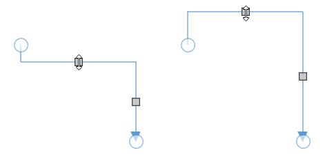
Orthogonal thumbs
- Orthogonal thumbs allow to adjust the length of adjacent segments by clicking and dragging it.
- When necessary, some segments are added or removed automatically, when dragging the segment. This is to maintain proper routing of orthogonality between segments.

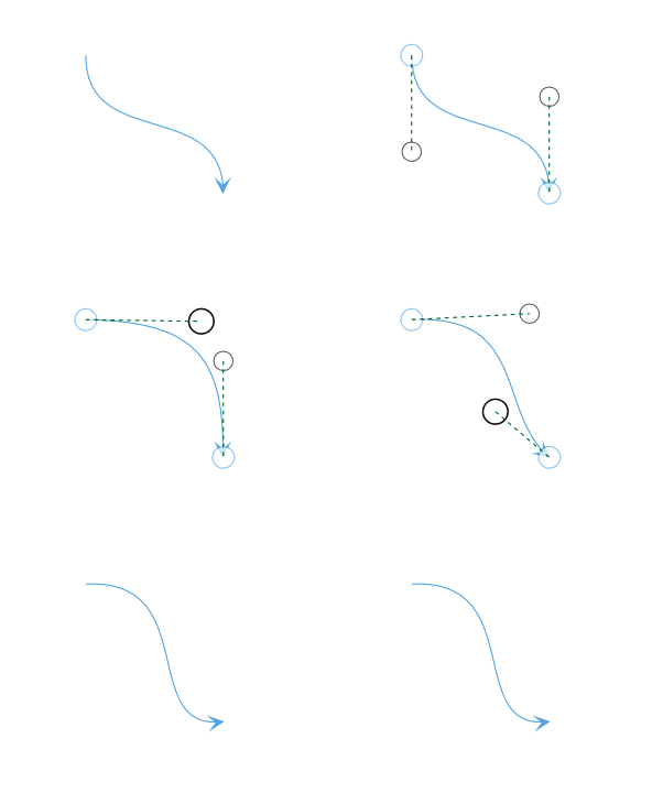
Bezier thumbs
- Bezier segments are annotated with two thumbs to represent the control points. Control points of the curve can be configured by clicking and dragging the control thumbs.

Constraints
The Constraints property of Connector allows to enable/disable certain features of Connectors. For more information about constraints, refer to Connector Constraints.
See Also
How to get or set the positions of the segments by programmatically?