Automatic Layouts in UWP Diagram (SfDiagram)
5 Dec 202416 minutes to read
SfDiagram provides support to auto-arrange the nodes in the Diagram area that is referred as Layout. It includes the following layout modes.
- Organization Chart
- Directed Tree Layout
- Radial Tree
We have explained the Automatic Layout with Employee class and DataSourceSettings.The followings are initial steps for all the Layout.
Create Class for Data
Now, you have to create a class, Employee with properties to store the employee’s information like Team, Role, ID, reporting person ID, etc. You also have to create a collection that stores a collection of the employees.
//Employee Business Object
public class Employee
{
	public string Team { get; set; }
	public string Role { get; set; }
	public int EmpiD { get; set; }
}

//Employee Collection
public class Employees : ObservableCollection<Employee>
{
}
Initialize Data Source Settings
<!--Initializes the DataSourceSettings -->
        <syncfusion:DataSourceSettings x:Key="DataSourceSettings" ParentId="Team" Id="Empid"
        DataSource="{StaticResource Employees}" />
Visualize the Node and Connector
<!--Style for the Node>-->
        <Style TargetType="syncfusion:Node">
            <Setter Property="UnitWidth" Value="100" />
            <Setter Property="UnitHeight" Value="50" />
            <Setter Property="FontSize" Value="14"></Setter>
            <Setter Property="Foreground" Value="Black"></Setter>
            <Setter Property="HorizontalContentAlignment" Value="Stretch"></Setter>
            <Setter Property="VerticalContentAlignment" Value="Stretch"></Setter>
            <Setter Property="Shape">
                <Setter.Value>
                    <RectangleGeometry Rect="10,10,10,10"></RectangleGeometry>
                </Setter.Value>
            </Setter>
            <Setter Property="ShapeStyle">
                <Setter.Value>
                    <Style TargetType="Path">
                        <Setter Property="Fill" Value="OliveDrab"></Setter>
                        <Setter Property="Stroke" Value="Black"></Setter>
                        <Setter Property="StrokeThickness" Value="1"></Setter>
                        <Setter Property="Stretch" Value="Fill"></Setter>
                    </Style>
                </Setter.Value>
            </Setter>
            <Setter Property="ContentTemplate">
                <Setter.Value>
                    <DataTemplate>
                        <Border>
                            <TextBlock Text="{Binding Role}" TextAlignment="Center"
                            TextWrapping="Wrap" Foreground="White" HorizontalAlignment="Center" 								VerticalAlignment="Center"/>
                        </Border>
                    </DataTemplate>
                </Setter.Value>
            </Setter>
        </Style>

        <!--< ! -Style for the Connector>-->
        <Style TargetType="syncfusion:Connector">
            <Setter Property="ConnectorGeometryStyle">
                <Setter.Value>
                    <Style TargetType="Path">
                        <Setter Property="Stroke" Value="Black" />
                        <Setter Property="StrokeThickness" Value="1" />
                    </Style>
                </Setter.Value>
            </Setter>
            <Setter Property="TargetDecorator" Value="null"></Setter>
        </Style>
Organization Layout
An organizational chart is a Diagram that displays the structure of an organization and relationships. To create an organizational chart, Type should be set as LayoutType.Organization. The following code example illustrates how to create an organizational chart.
_//Initializes data source_
<local:Employees x:Key="Employees">
<local:Employee Empid="0" Role="Project Management"></local:Employee>
<local:Employee Empid= "1"  Role= "R and D Team" Team= "0"/>
<local:Employee Empid= "3"  Role= "Philosophy" Team= "1"/>
<local:Employee Empid= "4"  Role= "Organization" Team= "1"/>
<local:Employee Empid= "5"  Role= "Technology" Team= "1"/>
<local:Employee Empid= "7"  Role= "Funding" Team= "1"/>
<local:Employee Empid= "8"  Role= "Resource Allocation" Team= "1"/>
<local:Employee Empid= "9"  Role= "Targeting" Team= "1"/>
<local:Employee Empid= "11"  Role= "Evaluation" Team= "1"/>
<local:Employee Empid= "156"  Role= "HR Team" Team= "0"/>
<local:Employee Empid= "13"  Role= "Recruitment" Team= "156"/>
<local:Employee Empid= "113"  Role= "Training" Team= "156"/>
<local:Employee Empid= "112"  Role= "Employee Relation" Team= "156"/>
<local:Employee Empid= "14"  Role= "Record Keeping" Team= "156"/>
<local:Employee Empid= "15"  Role= "Compensations and Benefits" Team= "12"/>
<local:Employee Empid= "16"  Role= "Compliances" Team= "12"/>
<local:Employee Empid= "17"  Role= "Production and Sales Team" Team= "0"/>
<local:Employee Empid= "119"  Role= "Design" Team= "17"/>
<local:Employee Empid= "19"  Role= "Operation" Team= "17"/>
<local:Employee Empid= "20"  Role= "Support" Team= "17"/>
<local:Employee Empid= "21"  Role= "Quality Assurance" Team= "17"/>
<local:Employee Empid= "23"  Role= "Customer Interaction" Team= "17"/>
<local:Employee Empid= "24"  Role= "Support and Maintenance" Team= "17"/>
<local:Employee Empid= "25"  Role= "Task Coordination" Team= "17"/>
</local:Employees>


<!--Initializes the Layout-->
<layout:DirectedTreeLayout x:Key="TreeLayout" HorizontalSpacing="90" VerticalSpacing="50"
SpaceBetweenSubTrees="20"Orientation="TopToBottom"/>

<layout:LayoutManager x:Key="LayoutManager"
Layout="{StaticResource TreeLayout}"/>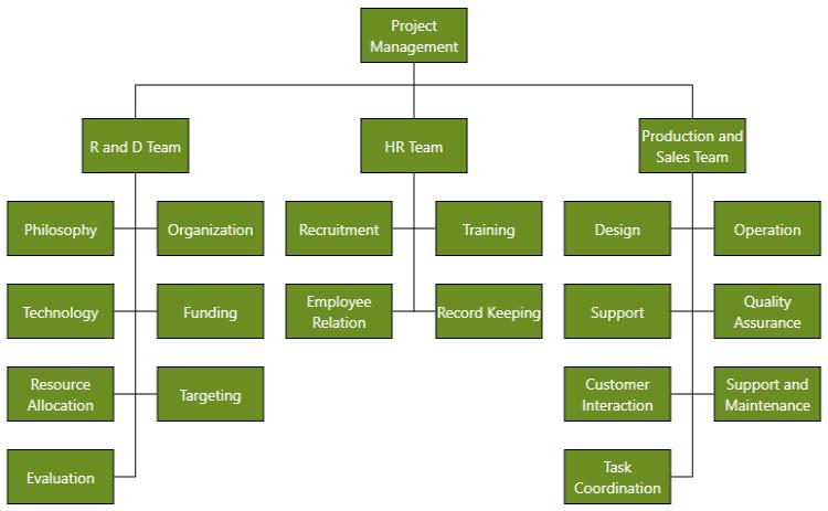
Organizational chart layout starts parsing from root and iterate through all its child elements. ‘GetLayoutInfo’ method provides necessary information of a Node’s children and the way to arrange (Orientation, Type etc.) them. You can customize the arrangements by overriding this function as explained.
Get Layout Info
User can change ChartType and Orientation by using GetLayoutInfo event of the SfDiagram. This event will fire for each Node added in Layout when the layout is getting updated. Default ChartType us Alternate and default orientation is Vertical. The following code example illustrates how to register an event and how to change ChartType and orientation.
Event Arguments:
| Event args | Property | Description |
|---|---|---|
| LayoutInfoArgs | Item | Added item when layout is getting updated. |
| Type | Gets or sets the organizational chart type. | |
| Orientation | Gets or sets the organizational chart orientation. |
// Registering an event

(diagramcontrol.Info as IGraphInfo).GetLayoutInfo += diagramcontrol_GetLayoutInfo;

void diagramcontrol_GetLayoutInfo(object sender, LayoutInfoArgs args)
{
	INode node = args.Item;
	args.Type = ChartType.Alternate;
	args.Orientation = Orientation.Vertical;
}
The following table illustrates the different chart orientations and chart types.
| Orientation | Type | Description | Example |
|---|---|---|---|
| Horizontal | Left | Arranges the child Nodes Horizontally at the Left side of Parent. | 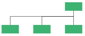 |
| Right | Arranges the child Nodes Horizontally at the Right side of Parent. | 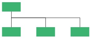 |
|
| Center | Arranges the child Nodes horizontally at the Center side of parent. | 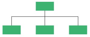 |
|
| Vertical | Left | Vertically arranges the children at the Left side of Parent. | 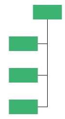 |
| Right | Vertically arranges the children at the Right side of Parent. | 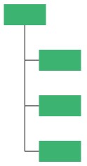 |
|
| Alternate | Vertically arranges the children at both Left and Right sides of Parent. | 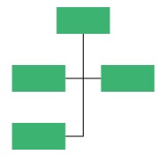 |
Directed-Tree Layout
The Directed-Tree layout mode enables you to arrange the Nodes in a tree like structure. This layout can be applied to any Diagram that comprises a directed tree graph with unique root and child Nodes. This creates the Diagrams easier because the Node position is determined automatically based on the connections. However, it is necessary to specify a layout root for the tree layout, as the Directed-Tree layout positions the Nodes based on the layout root.
To create the Directed Tree Layout, Type should be set as LayoutType.Hierarchical.
NOTE
SpaceBetweenSubTrees property of the DirectedTreeLayout will no longer efficient. Please use HorizontalSpacing and VerticalSpacing.
<local:Employees x:Key="Employees">
<local:Employee Empid="0" Role="Project Management"></local:Employee>
<local:Employee Empid= "1"  Role= "R and D Team" Team= "0"/>
<local:Employee Empid= "3"  Role= "Philosophy" Team= "1"/>
<local:Employee Empid= "4"  Role= "Organization" Team= "1"/>
<local:Employee Empid= "156"  Role= "HR Team" Team= "0"/>
<local:Employee Empid= "13"  Role= "Recruitment" Team= "156"/>
<local:Employee Empid= "113"  Role= "Training" Team= "156"/>
<local:Employee Empid= "17"  Role= "Production and Sales Team" Team= "0"/>
<local:Employee Empid= "119"  Role= "Design" Team= "17"/>
<local:Employee Empid= "19"  Role= "Operation" Team= "17"/>
</local:Employees>
<!--Initializes the Layout-->
<layout:DirectedTreeLayout x:Key="TreeLayout" HorizontalSpacing="90" VerticalSpacing="50"
SpaceBetweenSubTrees="20"Orientation="TopToBottom"/>

<layout:LayoutManager x:Key="LayoutManager"
Layout="{StaticResource TreeLayout}"/>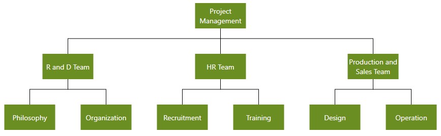
Radial-Tree Layout
The Radial-Tree Layout is a specification of the Directed Tree Layout Manager that employs a circular layout algorithm for locating the Diagram Nodes. The Radial-Tree Layout arranges Nodes in a circular layout, positioning the root Node at the center of the graph and the child Nodes in a circular fashion around the root. Sub-trees formed by the branching of child Nodes are located radically around the child Nodes. The arrangement results in an ever-expanding concentric arrangement with radial proximity to the root Node indicating the Node level in the hierarchy. However, it is necessary to specify a layout root for the tree layout, as the Radial-Tree Layout positions the Nodes based on the layout root.
<local:Employees x:Key="Employees">
	<local:Employee Empid="0" Role="Project Management"></local:Employee>
	<local:Employee Empid= "1"  Role= "R and D Team" Team= "0"/>
	<local:Employee Empid= "3"  Role= "Philosophy" Team= "1"/>
	<local:Employee Empid= "4"  Role= "Organization" Team= "1"/>
	<local:Employee Empid= "156"  Role= "HR Team" Team= "0"/>
	<local:Employee Empid= "13"  Role= "Recruitment" Team= "156"/>
	<local:Employee Empid= "113"  Role= "Training" Team= "156"/>
	<local:Employee Empid= "17"  Role= "Production Team" Team= "0"/>
	<local:Employee Empid= "119"  Role= "Design" Team= "17"/>
	<local:Employee Empid= "19"  Role= "Operation" Team= "17"/>
	<local:Employee Empid= "18"  Role= "Sales Team" Team= "0"/>
	<local:Employee Empid= "113"  Role= "Support and Maintenance" Team= "18"/>
	<local:Employee Empid= "117"  Role= "Customer Interaction" Team= "18"/>
</local:Employees>

<!--< ! -Style for the Node>-->
<Style TargetType="syncfusion:Node">
	<Setter Property="UnitWidth" Value="30" />
	<Setter Property="UnitHeight" Value="30" />
	<Setter Property="Shape">
	<Setter.Value>
		<EllipseGeometry RadiusX="10" RadiusY="10"></EllipseGeometry>
	</Setter.Value>
	</Setter>
	<Setter Property="ShapeStyle">
	<Setter.Value>
		<Style TargetType="Path">
			<Setter Property="Fill" Value="OliveDrab"></Setter>
			<Setter Property="Stretch" Value="Fill"></Setter>
		</Style>
	</Setter.Value>
	</Setter>
</Style>
Updating the Layout
When changes are made to content in the SfDiagram. For example, linking new Nodes or adding new Connectors, the layout had to be updated to create space for adding the new content. The following code example illustrates how to update the layout in the SfDiagram.
SfDiagram diagramcontrol = new SfDiagram();
//Update the Layout
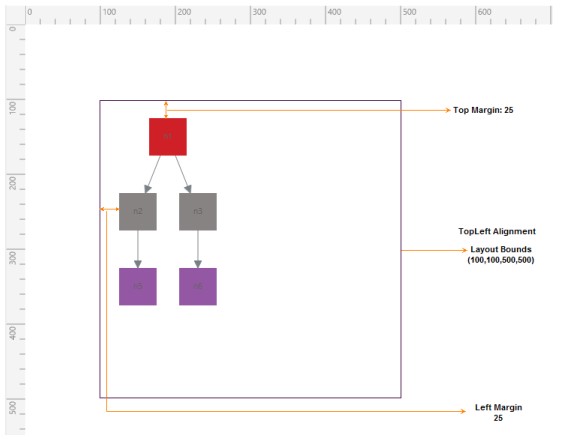
(diagramcontrol.LayoutManager.Layout as DirectedTreeLayout).UpdateLayout();Layout Bounds, Margins, and Alignments
Description
Diagram layouts can be arranged at the custom positions based upon the layout bounds, margins, and alignments.
Example
Layout Alignments and Bounds
diagramcontrol.LayoutManager = new LayoutManager()
{
    //Initializes the Layout
	Layout = new DirectedTreeLayout()
	{
       	   Type = LayoutType.Hierarchical,
	       HorizontalSpacing = 30,
	       VerticalSpacing = 50,
	       HorizontalAlignment = HorizontalAlignment.Left,
		   VerticalAlignment = VerticalAlignment.Top,
	       Bounds = new Rect(100, 100, 500, 500),
	       Margin = new Thickness(25, 25, 25, 25)
	}
};