How can I help you?
Shapes
Diagram provides support to add different kind of nodes. They are as follows.
- Text Node
- Image Node
- HTML Node
- Native Node
- Basic Shapes
- Flow Shapes
- BPMN Shapes
Text
Texts can be added to the Diagram as text nodes. For text nodes, the text node can be created with TextNode class . In addition, you need to define the TextBlock object that is used to define the TextNode to be added and to customize the appearance of that text. The following code illustrates how to create a text node.
<%--   Initializes Diagram--%>
        <ej:Diagram ID="Diagram" runat="server" Height="600px" Width="900px">
            <%--    Add the node to the nodes collection --%>
            <Nodes>
                <%-- Defines the Text node --%>
                <ej:TextNode OffsetX="100" OffsetY="100" Height="50" Width="100">
                    <%--   Set the text node properties--%>
                    <TextBlock Text="Text Node" FontColor="black" TextAlign="Center"></TextBlock>
                </ej:TextNode>
            </Nodes>
        </ej:Diagram>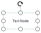
Image
Diagram allows to add images as image nodes. For image nodes,the image node can be created with ImageNode class. In addition, the Source property of node enables you to set the image source. The following code illustrates how an Image node is created.
<%--   Initializes Diagram--%>
        <ej:Diagram ID="Diagram" runat="server" Height="600px" Width="900px">
            <%--    Add the node to the nodes collection --%>
            <Nodes>
                <%-- Defines the Image node and sets url of the image--%>
                <ej:ImageNode OffsetX="100" OffsetY="100" Height="100" Width="100" Source="sample/syncfusion.png">
                </ej:ImageNode>
            </Nodes>
        </ej:Diagram>
HTML
HTML elements can be embedded in the Diagram through HTML type node. To create a HTML node, node can be created with HtmlNode class. In addition, you need to set the id of HTML template to the TemplateId property of node. The following code illustrates how an HTML node is created.
<!--dependency scripts-->
    <script src="http://borismoore.github.io/jsrender/jsrender.min.js"></script>
    <!—define HTML element-->
    <script id="htmlTemplate" type="text/x-jsrender">
        <div style="margin-left: 32px; margin-top: 18px">
            <input type="button" value="Button" />
        </div>
    </script>


        <%--   Initializes Diagram--%>
        <ej:Diagram ID="Diagram" runat="server" Height="600px" Width="900px">
            <%--    Add the node to the nodes collection --%>
            <Nodes>
                <%-- Defines the HTML node and sets id of HTML template--%>
                <ej:HtmlNode OffsetX="100" OffsetY="100" Height="100" Width="100" TemplateId ="htmlTemplate">
                </ej:HtmlNode>
            </Nodes>
        </ej:Diagram>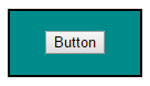
NOTE
HTML node cannot be exported to image format, like JPEG, PNG, and BMP. It is by design that while exporting, Diagram is drawn in a canvas. Further, this canvas is exported into image formats. Currently, drawing in a canvas equivalent from all possible HTML is not feasible. Hence, this limitation.
Native
Diagram provides support to embed SVG element into a node. To create a native node, the node can be created with NativeNode class. Also, you need to define the id of the SVG template by using the TemplateId property of node. The following code illustrates how a Native node is created.
<!--dependency scripts-->
    <script src="http://borismoore.github.io/jsrender/jsrender.min.js">
    </script>
    <!--define HTML element-->
    <script id="svgTemplate" type="text/x-jsrender">
        <g>
            <path d="M 58.813 0 H 3.182 L 30.998 24.141 L 58.813 0 Z
            M 32.644 34.425 C 32.133 34.87 31.567 35.095 31 35.095 S
            29.867 34.87 29.353 34.425 L 1 9.826V 60 H 61 V 9.826 L
            32.644 34.425Z"></path>
        </g>
    </script>


        <%--   Initializes Diagram--%>
        <ej:Diagram ID="Diagram" runat="server" Height="600px" Width="900px">
            <%--    Add the node to the nodes collection --%>
            <Nodes>
                <%-- Defines the native node and sets id of native template--%>
                <ej:NativeNode OffsetX="100" OffsetY="100" Height="100" Width="100" TemplateId ="svgTemplate">
                </ej:NativeNode>
            </Nodes>
        </ej:Diagram>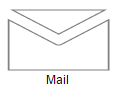
NOTE
Like HTML node, Native node also cannot be exported to image format. Fill color of native node can be overridden by the inline style or fill of the SVG element specified in the template.
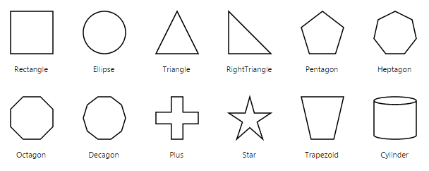
Basic Shapes
The Basic shapes are common shapes that are used to represent the geometrical information visually. Its Shape property can be set with any one of the built-in Basic Shapes.
The following code example illustrates how to create a basic shape.
<%--   Initializes Diagram--%>
        <ej:Diagram ID="Diagram" runat="server" Height="600px" Width="900px">
            <%--    Add the node to the nodes collection --%>
            <Nodes>
                <%-- Defines the basic shape and its properties --%>
                <ej:BasicShape OffsetX="100" OffsetY="100" Height="70" Width="100"
                    BorderWidth="2" BorderColor="black" CornerRadius="10" Shape="Rectangle">
                </ej:BasicShape>
            </Nodes>
        </ej:Diagram>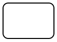
NOTE
When the
Shapeis not set for a basic shape, it is considered a “rectangle”.
Path
Path node is a commonly used basic shape that allows visually to represent the geometrical information. To create a path node, node can be created with PathNode class and PathData property. The PathData property of node allows you to define the path to be drawn. The following code illustrates how a Path node is created.
<%--   Initializes Diagram--%>
        <ej:Diagram ID="Diagram" runat="server" Height="600px" Width="900px">
            <%--    Add the node to the nodes collection --%>
            <Nodes>
                <%-- Defines the basic shape type as Path and PathData --%>
                <ej:BasicShape OffsetX="100" OffsetY="100" Height="70" Width="100"
                    BorderWidth="2" BorderColor="black" FillColor="darkcyan"
                    Shape="Path"
                    PathData="M35.2441,25 L22.7161,49.9937 L22.7161,0.006575
        L35.2441,25 z M22.7167,25 L-0.00131226,25 M35.2441,49.6337
        L35.2441,0.368951 M35.2441,25 L49.9981,25">
                </ej:BasicShape>
            </Nodes>
        </ej:Diagram>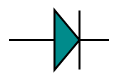
The list of basic shapes are as follows.
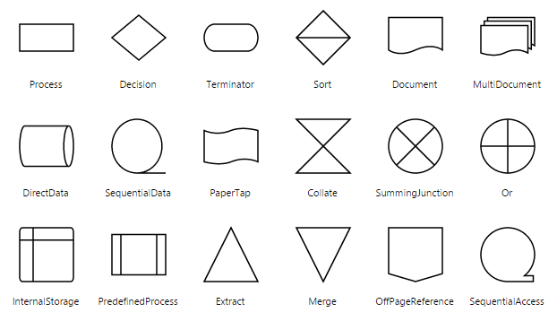
Flow Shapes
The flow shapes are used to represent the process flow. It is used for analyzing, designing, and managing for documentation process. To create a flow shape, node can be created with FlowShape class. Its Shape property can be set with any one of the built-in Flow Shapes and by default, it is considered as “Process”. The following code example illustrates how to create a flow shape.
<%--   Initializes Diagram--%>
        <ej:Diagram ID="Diagram" runat="server" Height="600px" Width="900px">
            <%--    Add the node to the nodes collection --%>
            <Nodes>
                <%-- Defines the FlowShape shape type as Path and Shape  --%>
                <ej:FlowShape OffsetX="100" OffsetY="100" Height="70" Width="100"
                    BorderWidth="2" BorderColor="black" Shape="Document">
                </ej:FlowShape>
            </Nodes>
        </ej:Diagram>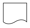
The list of flow shapes are as follows.
BPMN Shapes
BPMN shapes are used to represent the internal business procedure in a graphical notation and enables you to communicate the procedures in a standard manner. To create a BPMN shape, node can be created with BPMNNode class and its Shape should be set as any one of the built-in BPMN Shapes. The following code example illustrates how to create a simple business process.
<%--   Initializes Diagram--%>
        <ej:Diagram ID="Diagram" runat="server" Height="600px" Width="900px">
            <%--    Add the node to the nodes collection --%>
            <Nodes>
                <%-- Defines the FlowShape shape type, type of the Event as Path and Event  --%>
                <ej:BPMNNode OffsetX="100" OffsetY="100" Height="70" Width="100"
                    BorderWidth="2" BorderColor="black" Shape="Event" Event="End">
                </ej:BPMNNode>
            </Nodes>
        </ej:Diagram>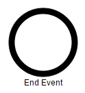
NOTE
The default value for the property
Shapeis “Event”.
The list of BPMN shapes are as follows.
| Shape | Image |
|---|---|
| Event |  |
| Gateway |  |
| Task |  |
| Message |  |
| DataSource |  |
| DataObject |  |
The BPMN shapes and its types are explained as follows.
Event
An event is notated with a circle and it represents an event in a business process. The type of events are as follows.
- Start
- End
- Intermediate
The Event property of the node allows you to define the type of the event. The default value of the Event is “Start”. The following code example illustrates how to create a BPMN Event.
<%--   Initializes Diagram--%>
        <ej:Diagram ID="Diagram" runat="server" Height="600px" Width="900px">
            <%--    Add the node to the nodes collection --%>
            <Nodes>
                <%-- Defines the FlowShape shape type, type of the Event as Path , Event and trigger  --%>
                <ej:BPMNNode OffsetX="100" OffsetY="100" Height="70" Width="100"
                    BorderWidth="2" BorderColor="black" Shape="Event" Event="End" Trigger="None">
                </ej:BPMNNode>
            </Nodes>
        </ej:Diagram>
| Event | Image |
|---|---|
| Start |  |
| NonInterruptingStart |  |
| Intermediate |  |
| NonInterruptingIntermediate |  |
| End |  |
Event triggers are notated as icons inside the circle and they represent the specific details of the process. The Triggers property of node allows you to set the type of trigger and by default, it is set as “None”. The following table illustrates the type of event triggers.
| Triggers | Image |
|---|---|
| Message |  |
| Compensation |  |
| Error |  |
| Escalation |  |
| Link |  |
| Multiple |  |
| Parallel |  |
| Signal |  |
| Timer |  |
Gateway
Gateway is used to control the flow of a process. It is represented as a diamond shape. To create a gateway, the Shape property of node should be set as “Gateway” and the Gateway property can be set with any of the appropriate Gateways. The following code example illustrates how to create a BPMN Gateway.
<%--   Initializes Diagram--%>
        <ej:Diagram ID="Diagram" runat="server" Height="600px" Width="900px">
            <%--    Add the node to the nodes collection --%>
            <Nodes>
                <%-- Defines the FlowShape shape type, type of the Event as Path , Event and GateWay  --%>
                <ej:BPMNNode OffsetX="100" OffsetY="100" Height="70" Width="100"
                    BorderWidth="2" BorderColor="black" Shape="Event" Event="End" Gateway="None">
                </ej:BPMNNode>
            </Nodes>
        </ej:Diagram>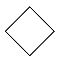
NOTE
By default, the
Gatewaywill be set as “None”.
There are several types of gateways as tabulated
| Gateways | Image |
|---|---|
| Complex |  |
| EventBased |  |
| Exclusive |  |
| Inclusive |  |
| Parallel |  |
Activity
The activity is the task that is performed in a business process. It is represented by a rounded rectangle.
There are two types of activities .They are listed as follows.
- Task – Occurs within a process and it is not broken down to finer level of detail.
- Subprocess – Occurs within a process and it is broken down to finer level of detail.
To create a BPMN activity, you need to set the Shape as “Activity”. You also need to set the type of the BPMN Activity by using the Activity property of node. By default, the type of the Activity is set as “Task”. The following code example illustrates how to create an activity.
<%--   Initializes Diagram--%>
        <ej:Diagram ID="Diagram" runat="server" Height="600px" Width="900px">
            <%--    Add the node to the nodes collection --%>
            <Nodes>
                <%-- Defines the FlowShape shape type, type of the Event as Path , Event and Activity  --%>
                <ej:BPMNNode OffsetX="100" OffsetY="100" Height="70" Width="100"
                    BorderWidth="2" BorderColor="black" Shape="Event" Event="End" Activity="Task">
                </ej:BPMNNode>
            </Nodes>
        </ej:Diagram>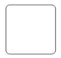
The different activities of BPMN process are listed as follows.
Tasks
The Task property of node allows you to define the Type of task such as sending, receiving, user based task etc… By default, the Type property of task is set as “None”. The following code illustrates how to create different types of BPMN tasks.
<%--   Initializes Diagram--%>
        <ej:Diagram ID="Diagram" runat="server" Height="600px" Width="900px">
            <%--    Add the node to the nodes collection --%>
            <Nodes>
                <%-- Defines the FlowShape shape type, type of the Event as Path , Event and Task  --%>
                <ej:BPMNNode OffsetX="100" OffsetY="100" Height="70" Width="100"
                    BorderWidth="2" BorderColor="black" Shape="Activity" Activity="Task">
                    <%-- Defines the type of the Task  --%>
                    <Task Type="Send"></Task>
                </ej:BPMNNode>
            </Nodes>
        </ej:Diagram>
The various types of BPMN tasks are tabulated as follows.
| Task Type | Image |
|---|---|
| Service |  |
| Send |  |
| Receive |  |
| Instantiating Receive |  |
| Manual |  |
| Business Rule |  |
| User |  |
| Script |  |
Loop
Loop is a task that is internally being looped. The Loop property of task allows you to define the type of loop. The default value for Loop is “None”.
<%--   Initializes Diagram--%>
        <ej:Diagram ID="Diagram" runat="server" Height="600px" Width="900px">
            <%--    Add the node to the nodes collection --%>
            <Nodes>
                <%-- Defines the FlowShape shape type, type of the Event as Path , Event and Task  --%>
                <ej:BPMNNode Name="BPMN1" OffsetX="100" OffsetY="100" Height="70" Width="100"
                    BorderWidth="2" BorderColor="black" Shape="Event" Activity="Task">
                    <%-- Sets the type of bpmn loops.  --%>
                    <Task Loop="Standard"></Task>
                </ej:BPMNNode>

                <ej:BPMNNode Name="BPMN2" OffsetX="300" OffsetY="100" Height="70" Width="100"
                    BorderWidth="2" BorderColor="black" Shape="Activity" Activity="SubProcess">
                    <%-- Sets the type of bpmn loops.  --%>
                    <Task Loop="Standard"></Task>
                </ej:BPMNNode>
            </Nodes>
        </ej:Diagram>
The following table contains various types of BPMN loops.
| Loops | Task | SubProcess |
|---|---|---|
| Standard |  |
 |
| SequenceMultiInstance |  |
 |
| ParallelMultiInstance |  |
 |
Compensation
Compensation is triggered when operation is partially failed and you can enable it with the Compensation property of task.
<%--   Initializes Diagram--%>
        <ej:Diagram ID="Diagram" runat="server" Height="600px" Width="900px">
            <%--    Add the node to the nodes collection --%>
            <Nodes>
                <%-- Defines the FlowShape shape type, type of the Event as Path , Event and Task  --%>
                <ej:BPMNNode Name="BPMN1" OffsetX="100" OffsetY="100" Height="70" Width="100"
                    BorderWidth="2" BorderColor="black" Shape="Activity" Activity="Task">
                    <%-- Sets the task Compensation  --%>
                    <Task Compensation="true"></Task>
                </ej:BPMNNode>

                <ej:BPMNNode Name="BPMN2" OffsetX="300" OffsetY="100" Height="70" Width="100"
                    BorderWidth="2" BorderColor="black" Shape="Activity" Activity="SubProcess">
                    <%-- Sets the task Compensation  --%>
                    <SubProcess Compensation ="true"></SubProcess>
                </ej:BPMNNode>
            </Nodes>
        </ej:Diagram>
Call
A call activity is a global sub-process that is reused at various points of the business flow and you can set it with the Call property of task.
<%--   Initializes Diagram--%>
        <ej:Diagram ID="Diagram" runat="server" Height="600px" Width="900px">
            <%--    Add the node to the nodes collection --%>
            <Nodes>
                <%-- Defines the FlowShape shape type, type of the Event as Path , Event and Task  --%>
                <ej:BPMNNode Name="task" OffsetX="100" OffsetY="100" Height="70" Width="100"
                    BorderWidth="2" BorderColor="black" Shape="Activity" Activity="Task">
                    <%-- Sets the task Call  --%>
                    <Task Call="true"></Task>
                </ej:BPMNNode>
            </Nodes>
        </ej:Diagram>
Ad-Hoc
An ad hoc subprocess is a group of tasks that are executed in any order or skipped in order to fulfill the end condition and you can set it with the Adhoc property of subprocess.
<%--   Initializes Diagram--%>
        <ej:Diagram ID="Diagram" runat="server" Height="600px" Width="900px">
            <%--    Add the node to the nodes collection --%>
            <Nodes>
                <%-- Defines the FlowShape shape type, type of the Event as Path , Event and Task  --%>
                <ej:BPMNNode Name="task" OffsetX="100" OffsetY="100" Height="70" Width="100"
                    BorderWidth="2" BorderColor="black" Shape="Activity" Activity="Task">
                    <%-- Sets the task Adhoc as true  --%>
                    <SubProcess Adhoc="true"></SubProcess>
                </ej:BPMNNode>
            </Nodes>
        </ej:Diagram>
Boundary
Boundary represents the type of task that is being processed. The Boundary property of sub process allows you to define the type of boundary. By default, it is set as “Default”.
<%--   Initializes Diagram--%>
        <ej:Diagram ID="Diagram" runat="server" Height="600px" Width="900px">
            <%--    Add the node to the nodes collection --%>
            <Nodes>
                <%-- Defines the FlowShape shape type, type of the Event as Path , Event and Task  --%>
                <ej:BPMNNode Name="task" OffsetX="100" OffsetY="100" Height="70" Width="100"
                    BorderWidth="2" BorderColor="black" Shape="Activity" Activity="Task">
                    <%-- Sets the task Boundary  --%>
                    <SubProcess Boundary="Call"></SubProcess>
                </ej:BPMNNode>
            </Nodes>
        </ej:Diagram>
The following table contains various types of BPMN boundaries.
| Boundary | Image |
|---|---|
| Call | 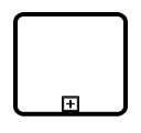 |
| Event | 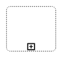 |
| Default | 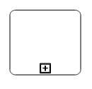 |
Data
A data object represents information flowing through the process, such as data placed into the process, data resulting from the process, data that needs to be collected, or data that must be stored. To define a data object, set the Shape as “Dataobject”. You can create multiple instances of data object with the Collection property of node.
<%--   Initializes Diagram--%>
        <ej:Diagram ID="Diagram" runat="server" Height="600px" Width="900px">
            <%--    Add the node to the nodes collection --%>
            <Nodes>
                <%-- Defines the FlowShape shape type and Sets collection as true when Dataobject is not a Single instance --%>
                <ej:BPMNNode Name="task" OffsetX="100" OffsetY="100" Height="70" Width="100"
                    BorderWidth="2" BorderColor="black" Shape="DataObject" Collection="true">
                </ej:BPMNNode>
            </Nodes>
        </ej:Diagram>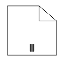
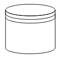
Datasource
DataSource is used to store or access data associated with a business process. To create a data source, set the Shape as “Datasource”. The following code example illustrate how to create data source.
<%--   Initializes Diagram--%>
        <ej:Diagram ID="Diagram" runat="server" Height="600px" Width="900px">
            <%--    Add the node to the nodes collection --%>
            <Nodes>
                <%-- Defines the FlowShape shape type--%>
                <ej:BPMNNode Name="task" OffsetX="100" OffsetY="100" Height="70" Width="100"
                    BorderWidth="2" BorderColor="black" Shape="DataSource" >
                </ej:BPMNNode>
            </Nodes>
        </ej:Diagram>