Decorators
Decorators are arrowheads/end caps set via the DecoratorShape enumeration. Connectors and lines support the following decorator shapes:
- Circle
- CircleCross
- CircleReverseArrow
- Cross45
- Cross90
- CrossReverseArrow
- Custom
- Diamond
- DimensionLine
- DoubleArrow
- DoubleCross
- Filled45Arrow
- Filled60Arrow
- FilledCircle
- FilledDiamond
- FilledFancyArrow
- FilledSquare
- None
- Open45Arrow
- Open60Arrow
- OpenFancyArrow
- ReverseArrow
- ReverseDoubleArrow
- Square
Connecting Two Nodes with Line Connector
The following code example illustrates how to create links between two nodes.
protected void Page_Load(object sender, EventArgs e)
{
	Syncfusion.Windows.Forms.Diagram.Ellipse ellipse = new Syncfusion.Windows.Forms.Diagram.Ellipse(10, 10, 110, 70);
	Syncfusion.Windows.Forms.Diagram.Rectangle rectangle = new Syncfusion.Windows.Forms.Diagram.Rectangle(300, 50, 50, 80);
	Syncfusion.Windows.Forms.Diagram.LineConnector lineconnector = new Syncfusion.Windows.Forms.Diagram.LineConnector(new System.Drawing.PointF(10, 200), new System.Drawing.PointF(300, 250));
	this.diagram1.Model.AppendChild(ellipse);
	this.diagram1.Model.AppendChild(rectangle);
	ellipse.CentralPort.TryConnect(lineconnector.HeadEndPoint);
	rectangle.CentralPort.TryConnect(lineconnector.TailEndPoint);
	this.diagram1.Model.AppendChild(lineconnector);
}
Protected Sub Page_Load(ByVal sender As Object, ByVal e As EventArgs)
Dim ellipse As New Syncfusion.Windows.Forms.Diagram.Ellipse(10, 10, 110, 70)
Dim rectangle As New Syncfusion.Windows.Forms.Diagram.Rectangle(300, 50, 50, 80)
Dim lineconnector As New Syncfusion.Windows.Forms.Diagram.LineConnector(New System.Drawing.PointF(10, 200), New System.Drawing.PointF(300, 250))
Me.diagram1.Model.AppendChild(ellipse)
Me.diagram1.Model.AppendChild(rectangle)
ellipse.CentralPort.TryConnect(lineconnector.HeadEndPoint)
rectangle.CentralPort.TryConnect(lineconnector.TailEndPoint)
Me.diagram1.Model.AppendChild(lineconnector)
End Sub
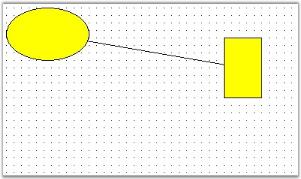
Customizing Connector Appearance
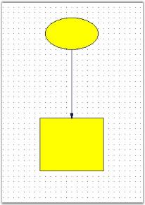
You can change the appearance of the connectors using its properties through code. The following code example illustrates the line properties.
The following table lists the properties used to customize a connector’s decorators and line style:
| Property |
Description |
Data Type |
| DecoratorShape |
Gets or sets the shape of the decorator at the head or tail end of the connector. |
DecoratorShape |
| Container |
Reference to the container node the decorator is attached to. |
Node |
| GraphicsPath |
Gets the graphics path that defines the visual representation of the decorator. |
GraphicsPath |
| FillStyle |
Properties for creating a brush to fill the decorator with. |
FillStyle |
| Size |
Gets or sets the width and height of the decorator. |
SizeF |
| IsPathClosed |
Gets a value indicating whether the decorator graphics path is closed (protected). |
bool |
| LineStyle |
Line drawing properties for the connector; determines the configuration of the pen used to outline the connector. |
LineStyle |
</table>
protected void Page_Load(object sender, EventArgs e)
{
	Syncfusion.Windows.Forms.Diagram.Ellipse ellipse = new Syncfusion.Windows.Forms.Diagram.Ellipse(160, 60, 100, 60);
	Syncfusion.Windows.Forms.Diagram.Rectangle rectangle = new Syncfusion.Windows.Forms.Diagram.Rectangle(150, 250, 120, 100);
	Syncfusion.Windows.Forms.Diagram.LineConnector lineconnector = new Syncfusion.Windows.Forms.Diagram.LineConnector(new System.Drawing.PointF(10, 200), new System.Drawing.PointF(300, 250));
	this.diagram1.Model.AppendChild(ellipse);
	this.diagram1.Model.AppendChild(rectangle);
	ellipse.CentralPort.TryConnect(lineconnector.TailEndPoint);
	rectangle.CentralPort.TryConnect(lineconnector.HeadEndPoint);
	this.diagram1.Model.AppendChild(lineconnector);
	lineconnector.HeadDecorator.DecoratorShape = DecoratorShape.Filled45Arrow;
	lineconnector.LineStyle.LineColor = Color.MidnightBlue;
	lineconnector.HeadDecorator.FillStyle.Color = Color.MidnightBlue;
	lineconnector.HeadDecorator.Size = new SizeF(10, 5);
}
Protected Sub Page_Load(ByVal sender As Object, ByVal e As EventArgs)
Dim ellipse As New Syncfusion.Windows.Forms.Diagram.Ellipse(160, 60, 100, 60)
Dim rectangle As New Syncfusion.Windows.Forms.Diagram.Rectangle(150, 250, 120, 100)
Dim lineconnector As New Syncfusion.Windows.Forms.Diagram.LineConnector(New System.Drawing.PointF(10, 200), New System.Drawing.PointF(300, 250))
Me.diagram1.Model.AppendChild(ellipse)
Me.diagram1.Model.AppendChild(rectangle)
ellipse.CentralPort.TryConnect(lineconnector.TailEndPoint)
rectangle.CentralPort.TryConnect(lineconnector.HeadEndPoint)
Me.diagram1.Model.AppendChild(lineconnector)
lineconnector.HeadDecorator.DecoratorShape = DecoratorShape.Filled45Arrow
lineconnector.LineStyle.LineColor = Color.MidnightBlue
lineconnector.HeadDecorator.FillStyle.Color = Color.MidnightBlue
lineconnector.HeadDecorator.Size = New SizeF(10, 5)
End Sub
## Rounded Corner
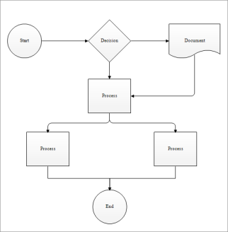
You can change the look of connectors ([Orthogonal](https://help.syncfusion.com/cr/windowsforms/Syncfusion.Windows.Forms.Diagram.OrthogonalConnector.html#), [OrgLine](https://help.syncfusion.com/cr/windowsforms/Syncfusion.Windows.Forms.Diagram.OrgLineConnector.html#), [Polyline](https://help.syncfusion.com/cr/windowsforms/Syncfusion.Windows.Forms.Diagram.Polyline.html#)) by providing rounded corners to connectors.
The [EnableRoundedCorner](https://help.syncfusion.com/cr/windowsforms/Syncfusion.Windows.Forms.Diagram.ConnectorBase.html#Syncfusion_Windows_Forms_Diagram_ConnectorBase_EnableRoundedCorner) property is used to enable rounded corners for a connector, and the [CurveRadius](https://help.syncfusion.com/cr/windowsforms/Syncfusion.Windows.Forms.Diagram.OrgLineConnector.html#Syncfusion_Windows_Forms_Diagram_OrgLineConnector_CurveRadius) connector property is used to set the radius for the rounded corner curve respectively.
### Use Case Scenario
This is used to change the visual style of connectors.
|
Property |
Description |
Data Type |
Default Value |
|
EnableRoundedCorner
|
Enables or disables rounded corner for a connector. |
bool |
false |
|
CurveRadius
|
Gets or sets the radius for the rounded corner curve of a connector. Valid values are non-negative floats. |
float |
0 |
The following code illustrates how to change the look of a connector by using the [EnableRoundedCorner](https://help.syncfusion.com/cr/windowsforms/Syncfusion.Windows.Forms.Diagram.ConnectorBase.html#Syncfusion_Windows_Forms_Diagram_ConnectorBase_EnableRoundedCorner) and [CurveRadius](https://help.syncfusion.com/cr/windowsforms/Syncfusion.Windows.Forms.Diagram.OrgLineConnector.html#Syncfusion_Windows_Forms_Diagram_OrgLineConnector_CurveRadius) properties.
OrthogonalConnector orthogonal = new OrthogonalConnector(new PointF(100, 100), new PointF(300, 300));

// Enables rounded corner for the connector.
orthogonal.EnableRoundedCorner = true;

// Sets the radius of the rounded corner curve.
orthogonal.CurveRadius = 10;

diagram1.Model.AppendChild(orthogonal);
Dim orthogonal As New OrthogonalConnector(New PointF(100, 100), New PointF(300, 300))

'Enables rounded corner for the connector.
orthogonal.EnableRoundedCorner = True

'Sets the radius of the rounded corner curve.
orthogonal.CurveRadius = 10

diagram1.Model.AppendChild(orthogonal)
## Line Bridging
Line bridging provides the visual effect such that the links jump over other links that are found in its way with lower [Z-order](https://help.syncfusion.com/cr/windowsforms/Syncfusion.Windows.Forms.Diagram.Node.html#Syncfusion_Windows_Forms_Diagram_Node_ZOrder), preventing the links from intersecting each other and making the connections clearer. The connector will also create the same visual effect when it jumps over any port. This is done by enabling the [LineBridgingEnabled](https://help.syncfusion.com/cr/windowsforms/Syncfusion.Windows.Forms.Diagram.ConnectorBase.html#Syncfusion_Windows_Forms_Diagram_ConnectorBase_LineBridgingEnabled) property. Default value is _false_.
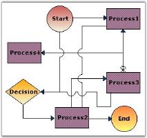
The below table lists the properties which controls the appearance of the bridge.
|
Property |
Description |
Default Value |
|
LineBridgingEnabled
|
Enables or disables line bridging for a connector or the diagram. |
false |
|
LineBridgeSize
|
Allows to set the size of the bridge when the links intersect each other. |
16 |
|
BridgeStyle
|
Specifies the type of bridge to be applied. The value when set, applies to all the links that are drawn on the diagram. The links will bridge over the other link only when its Z-order
value is high. The options include the following:
- Arc
- Gap
- Square
- Side2
- Side3
- Side4
- Side5
- Side6
- Side7
|
Arc |
Programmatically it can be set as follows:
this.diagram1.Model.LineBridgeSize = 5;

//enabling for model
this.diagram1.Model.LineBridgingEnabled = true;

LineConnector link = new LineConnector(PointF.Empty, new PointF(200,200));

//enabling for link object
link.LineBridgingEnabled = true;

this.diagram1.Model.BridgeStyle = BridgeStyle.Square;
Me.diagram1.Model.LineBridgeSize = 5

'enabling for model
Me.diagram1.Model.LineBridgingEnabled = True

Dim link As LineConnector = New LineConnector(PointF.Empty, New PointF(200, 200))

'enabling for link object
link.LineBridgingEnabled = True

Me.diagram1.Model.BridgeStyle = BridgeStyle.Square
N> In the above code snippets, link refers to the instance of the Link node.
## Line Routing
When a link is drawn between two nodes, by enabling the [LineRoutingEnabled](https://help.syncfusion.com/cr/windowsforms/Syncfusion.Windows.Forms.Diagram.ConnectorBase.html#Syncfusion_Windows_Forms_Diagram_ConnectorBase_LineRoutingEnabled) property of that link and the diagram view, and if any other node is found in between them, the line will be automatically re-routed around those nodes.
|
Property |
Description |
|
LineRoutingEnabled
|
Specifies whether the links must be re-routed when nodes are found in the path. Default value is false. |
Programmatically it can be set as follows:
//enabling for model
this.diagram1.Model.LineRoutingEnabled = true;

LineConnector link = new LineConnector(PointF.Empty, new PointF(200,200));
//enabling for link object
link.LineRoutingEnabled = true;
'enabling for model
Me.diagram1.Model.LineRoutingEnabled = True

Dim link As LineConnector = New LineConnector(PointF.Empty, New PointF(200, 200))
'enabling for link object
link.LineRoutingEnabled = True
N> In the above code snippet, link refers to the instance of the Link node.
N>
N> Only when [LineRoutingEnabled](https://help.syncfusion.com/cr/windowsforms/Syncfusion.Windows.Forms.Diagram.ConnectorBase.html#Syncfusion_Windows_Forms_Diagram_ConnectorBase_LineRoutingEnabled) property is set to true, [LineRouter](https://help.syncfusion.com/cr/windowsforms/Syncfusion.Windows.Forms.Diagram.Model.html#Syncfusion_Windows_Forms_Diagram_Model_LineRouter) properties will be enabled.
### Distance and Routing Mode Settings
To customize the distance between the connectors and the obstacles, and the type of routing to use, the [LineRouter](https://help.syncfusion.com/cr/windowsforms/Syncfusion.Windows.Forms.Diagram.Model.html#Syncfusion_Windows_Forms_Diagram_Model_LineRouter) collection property should be handled. The below properties are available for the [LineRouter](https://help.syncfusion.com/cr/windowsforms/Syncfusion.Windows.Forms.Diagram.Model.html#Syncfusion_Windows_Forms_Diagram_Model_LineRouter) Collection property.
|
Line Router Property |
Description |
Default Value |
|
DistanceToObstacles
|
Specifies the distance from routing connector to the obstacle. |
10 |
|
RoutingMode
|
Specifies the routing mode. The options include Inactive (routing disabled), Automatic (links re-routed automatically around obstacles), and SemiAutomatic (links re-routed only on user interaction). |
Inactive |
Programmatically it can be set as follows.
this.diagram1.Model.LineRouter.DistanceToObstacles = 20;
this.diagram1.Model.LineRouter.RoutingMode = RoutingMode.Automatic;
Me.diagram1.Model.LineRouter.DistanceToObstacles = 20
Me.diagram1.Model.LineRouter.RoutingMode = RoutingMode.Automatic
The [LineBridgingEnabled](https://help.syncfusion.com/cr/windowsforms/Syncfusion.Windows.Forms.Diagram.ConnectorBase.html#Syncfusion_Windows_Forms_Diagram_ConnectorBase_LineBridgingEnabled), [LineRoutingEnabled](https://help.syncfusion.com/cr/windowsforms/Syncfusion.Windows.Forms.Diagram.ConnectorBase.html#Syncfusion_Windows_Forms_Diagram_ConnectorBase_LineRoutingEnabled) properties can be set for the diagram, in which case it will be automatically applied to all the links added to the model. Else it can be enabled only for the required links individually.
### Marking Nodes as Obstacles
When line routing is enabled, make sure to set the [TreatAsObstacle](https://help.syncfusion.com/cr/windowsforms/Syncfusion.Windows.Forms.Diagram.Node.html#Syncfusion_Windows_Forms_Diagram_Node_TreatAsObstacle) property of the objects to true, to avoid the links running over them. The default value is _false_. If not set for an object, then that node will not be considered as an obstacle and the link will pass over it.
|
Property |
Description |
Default Value |
|
TreatAsObstacle
|
Gets or sets a value indicating whether the node should be treated as an obstacle for line routing. |
false |
Programmatically it can be set as follows:
circle.TreatAsObstacle = true;
circle.TreatAsObstacle = True
In the above code snippets, the [TreatAsObstacle](https://help.syncfusion.com/cr/windowsforms/Syncfusion.Windows.Forms.Diagram.Node.html#Syncfusion_Windows_Forms_Diagram_Node_TreatAsObstacle) property is set to the circle object.