UML Class Diagram in Blazor Diagram Component
A UML class diagram is a visual blueprint that represents classes, their properties, operations, and relationships in a single visual model. It is one of the most widely used UML diagram types because it maps closely to object-oriented programming concepts such as classes, interfaces, enumerations, inheritance, and associations.
The SfDiagramComponent in the Syncfusion® Blazor suite supports creating and visualizing UML class diagrams. It provides classifier nodes such as classes, interfaces, and enumerations, and relationship connectors such as association, aggregation, composition, inheritance, dependency, and realization.In the Blazor Diagram component, classifier nodes are created using UmlClassifierShape, while relationships are created using RelationShip connectors.
UML Class Diagram Elements
A UML class diagram uses several core elements to represent and communicate object-oriented designs. This section introduces the fundamental elements of a UML class diagram, with detailed API configuration for each element provided in subsequent topics.
Classifiers
A classifier represents a named type in a UML class diagram and serves as the primary building block. To create a classifier node, assign a UmlClassifierShape to the Shape property of a Node. Then set the Classifier property to one of the ClassifierShape enum values.
| Classifier | Description |
|---|---|
| ClassifierShape.Class | Represents an object type with attributes and operations. |
| ClassifierShape.Interface | Represents a contract that can define attributes and operations. |
| ClassifierShape.Enumeration | Represents a fixed set of named values. |
Attributes, Operations, and Parameters
A UML class or interface node is visually divided into sections called compartments, each serving a distinct purpose:
-
Attributes represent data members or properties of the class. For example,
- name : string. -
Operations represent behaviors or methods that the class exposes. For example,
+ Move(speed : int) : void. -
Parameters are the input values passed to an operation. For example,
speed : int. -
Visibility defines the access level of an attribute or operation and is denoted by symbols:
+(public),-(private),#(protected), and~(package).
Create UML Classifier Nodes
This section explains how to create each supported UML classifier node type: class, interface, and enumeration.
Create a UML Class
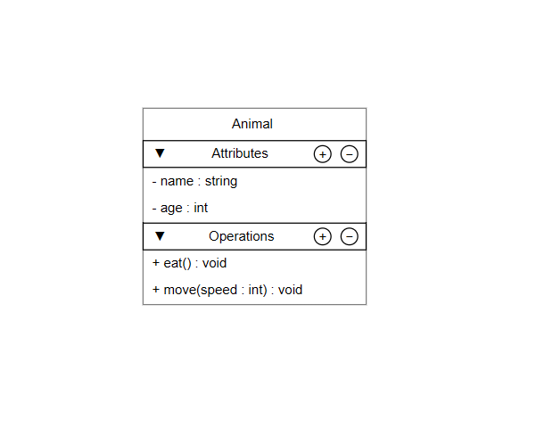
A UML class node renders the class name, attributes, and operations in separate compartments. To create a class node, set the Classifier property to ClassifierShape.Class and define the Attributes and Methods details using the ClassShape property.
The following properties can be used to configure UML class attributes and operations:
| Property | Description |
|---|---|
Name |
Specifies the member name. |
Type |
Specifies the data type of an attribute or the return type of an operation. |
Scope |
Specifies the visibility of the member. The default value is UmlScope.Public. |
IsSeparator |
When set to true, renders a horizontal divider instead of a member row. |
SeparatorStyle |
Defines the style applied to the separator line. |
Parameters |
Specifies the collection of parameters for an operation. Each parameter is represented by a UmlTypedElement and is displayed in the format name : type. |
@using Syncfusion.Blazor.Diagram

<SfDiagramComponent Height="600px" Nodes="@nodes">
</SfDiagramComponent>

@code {
    DiagramObjectCollection<Node> nodes = new DiagramObjectCollection<Node>();

    protected override void OnInitialized()
    {
        nodes.Add(new Node()
        {
            ID = "classNode",
            OffsetX = 250,
            OffsetY = 250,
            Shape = new UmlClassifierShape()
            {
                Classifier = ClassifierShape.Class,
                ClassShape = new UmlClass()
                {
                    Name = "Animal",
                    Attributes = new DiagramObjectCollection<UmlClassAttribute>()
                    {
                        new UmlClassAttribute() { Name = "name", Type = "string", Scope = UmlScope.Private },
                        new UmlClassAttribute() { Name = "age", Type = "int", Scope = UmlScope.Private }
                    },
                    Methods = new DiagramObjectCollection<UmlClassMethod>()
                    {
                        new UmlClassMethod() { Name = "eat", Type = "void", Scope = UmlScope.Public },
                        new UmlClassMethod()
                        {
                            Name = "move",
                            Type = "void",
                            Scope = UmlScope.Public,
                            Parameters = new DiagramObjectCollection<UmlTypedElement>()
                            {
                                new UmlTypedElement() { Name = "speed", Type = "int" }
                            }
                        }
                    }
                }
            }
        });
    }
}
A complete working sample can be downloaded from GitHub.
Create a UML Interface
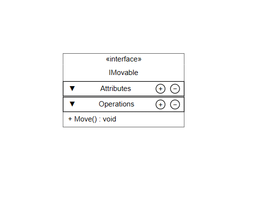
A UML interface node displays the «interface» stereotype above the interface name. It represents a contract rather than an implementation and supports defining attributes and operations. To create an interface node, set the Classifier property to ClassifierShape.Interface and define the interface details using the InterfaceShape property.
For details on attributes and operations properties, refer to the UML class section.
@using Syncfusion.Blazor.Diagram

<SfDiagramComponent Height="600px" Nodes="@nodes">
</SfDiagramComponent>

@code {
    DiagramObjectCollection<Node> nodes = new DiagramObjectCollection<Node>();

    protected override void OnInitialized()
    {
        nodes.Add(new Node()
        {
            ID = "interfaceNode",
            OffsetX = 250,
            OffsetY = 250,
            Width = 200,
            Shape = new UmlClassifierShape()
            {
                Classifier = ClassifierShape.Interface,
                InterfaceShape = new UmlInterface()
                {
                    Name = "IMovable",
                    Methods = new DiagramObjectCollection<UmlClassMethod>()
                    {
                        new UmlClassMethod() { Name = "Move", Type = "void", Scope = UmlScope.Public }
                    }
                }
            }
        });
    }
}
A complete working sample can be downloaded from GitHub.
Create a UML Enumeration
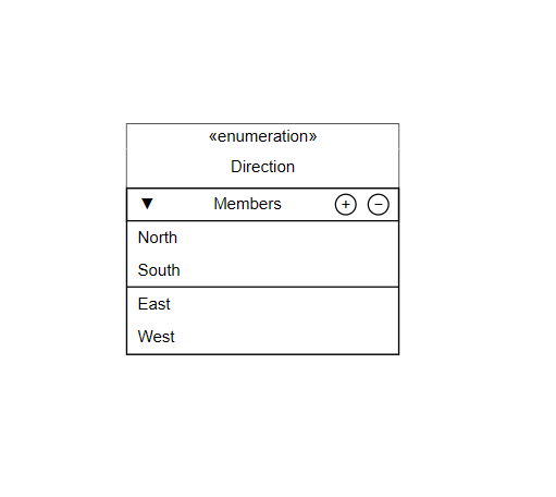
A UML enumeration node displays the «enumeration» stereotype above the enumeration name, followed by a members section that lists its named constants. To create an enumeration node, set the Classifier property to ClassifierShape.Enumeration and define the enumeration details using the EnumerationShape property.
The following properties can be used to configure members in UML enumeration:
| Property | Description |
|---|---|
Name |
Specifies the literal name displayed in the members section. |
IsSeparator |
When set to true, renders a horizontal divider in the members section. |
SeparatorStyle |
Defines the style applied to the separator line. |
@using Syncfusion.Blazor.Diagram

<SfDiagramComponent Height="600px" Nodes="@nodes">
</SfDiagramComponent>

@code {
    DiagramObjectCollection<Node> nodes = new DiagramObjectCollection<Node>();

    protected override void OnInitialized()
    {
        nodes.Add(new Node()
        {
            ID = "enumNode",
            OffsetX = 250,
            OffsetY = 250,
            Width = 200,
            Shape = new UmlClassifierShape()
            {
                Classifier = ClassifierShape.Enumeration,
                EnumerationShape = new UmlEnumeration()
                {
                    Name = "Direction",
                    Members = new DiagramObjectCollection<UmlEnumerationMember>()
                    {
                        new UmlEnumerationMember() { Name = "North" },
                        new UmlEnumerationMember() { Name = "South" },
                        new UmlEnumerationMember() { IsSeparator = true },
                        new UmlEnumerationMember() { Name = "East" },
                        new UmlEnumerationMember() { Name = "West" }
                    }
                }
            }
        });
    }
}
A complete working sample can be downloaded from GitHub.
The
UmlClassifierShapeautomatically adjusts its height based on the number of rows in each section, eliminating the need to set an explicitHeight. UML classifier nodes can be resized only from the right side (East resize handle). Rotation and corner resize handles are not supported.
Customize UML Classifier Appearance
The Blazor Diagram component provides styling options for each visual element of a UML classifier node, including the classifier header, attributes, and operations.
Customize the Classifier Header
The HeaderStyle property of UmlClassifierShape accepts a TextStyle object that controls the background fill, text color, font weight, and other visual properties of the classifier name header compartment.
@using Syncfusion.Blazor.Diagram

<SfDiagramComponent Height="600px" Nodes="@nodes">
</SfDiagramComponent>

@code {
    DiagramObjectCollection<Node> nodes = new DiagramObjectCollection<Node>();

    protected override void OnInitialized()
    {
        nodes.Add(new Node()
        {
            OffsetX = 250,
            OffsetY = 250,
            Width = 200,
            Shape = new UmlClassifierShape()
            {
                // Customize style for the header(top compartment)
                HeaderStyle = new TextStyle()
                {
                    Fill  = "#1565C0",
                    Color = "white"
                }
            }
        });
    }
}
Customize Section Headers
Each compartment — Attributes, Operations, and Members — has a header row configurable through UmlSectionHeaderSettings. Assign a UmlSectionHeaderSettings instance to AttributeHeaderSettings, MethodHeaderSettings, or MemberHeaderSettings on the UmlClass, UmlInterface, or UmlEnumeration shape to control the section label, style, action buttons, and expand or collapse behavior.
| Property | Description |
|---|---|
| HeaderText | Specifies the text label for the section header. |
| Style | Defines the visual style for the section header row. |
| EnableAddAction | Shows or hides the + button. The default value is true. |
| EnableRemoveAction | Shows or hides the – button. The default value is true. |
| IsExpanded | Specifies whether the section content is visible. The default value is true. |
| ShowExpandCollapseIcon | Shows or hides the expand or collapse icon. The default value is true. |
@using Syncfusion.Blazor.Diagram

<SfDiagramComponent Height="600px" Nodes="@nodes">
    <SnapSettings Constraints="SnapConstraints.None"></SnapSettings>
</SfDiagramComponent>

@code {
    DiagramObjectCollection<Node> nodes = new DiagramObjectCollection<Node>();

    protected override void OnInitialized()
    {
        nodes.Add(new Node()
        {
            ID = "customerNode",
            OffsetX = 250,
            OffsetY = 300,
            Width = 220,
            Shape = new UmlClassifierShape()
            {
                Classifier = ClassifierShape.Class,
                HeaderStyle = new TextStyle() { Fill = "#334155", Color = "#FFFFFF", Bold = true },
                ClassShape = new UmlClass()
                {
                    Name = "Customer",
                    AttributeHeaderSettings = new UmlSectionHeaderSettings()
                    {
                        HeaderText = "Properties",
                        ShowExpandCollapseIcon = false,
                        IsExpanded = true,
                        Style = new TextStyle() { Fill = "#475569", Color = "#FFFFFF", Bold = true }
                    },
                    MethodHeaderSettings = new UmlSectionHeaderSettings()
                    {
                        HeaderText = "Operations",
                        ShowExpandCollapseIcon = true,
                        EnableAddAction = true,
                        EnableRemoveAction = true,
                        IsExpanded = true,
                        Style = new TextStyle() { Fill = "#64748B", Color = "#FFFFFF", Bold = true }
                    },
                    Attributes = new DiagramObjectCollection<UmlClassAttribute>()
                    {
                        new UmlClassAttribute() { Name = "CustomerId", Type = "int", Scope = UmlScope.Public, Style = new TextStyle() { Fill = "#E2E8F0", Color = "#334155" } },
                        new UmlClassAttribute() { Name = "Email", Type = "string", Scope = UmlScope.Private, Style = new TextStyle() { Fill = "#E2E8F0", Color = "#334155" } }
                    },
                    Methods = new DiagramObjectCollection<UmlClassMethod>()
                    {
                        new UmlClassMethod() { Name = "PlaceOrder", Type = "void", Scope = UmlScope.Public, Style = new TextStyle() { Fill = "#F8FAFC", Color = "#475569" } },
                        new UmlClassMethod() { Name = "UpdateProfile", Type = "bool", Scope = UmlScope.Public, Style = new TextStyle() { Fill = "#F8FAFC", Color = "#475569" } },
                        new UmlClassMethod() { Name = "GetOrderHistory", Type = "List<Order>", Scope = UmlScope.Public, Style = new TextStyle() { Fill = "#F8FAFC", Color = "#475569" } }
                    }
                }
            }
        });
    }
}
A complete working sample can be downloaded from GitHub.
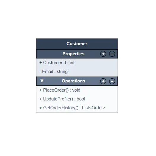
Customize Attributes, Operations, and Members
Individual attributes, operations, and enumeration members support row-level styling. Assign a TextStyle object to the Style property of any UmlClassAttribute, UmlClassMethod, or UmlEnumerationMember instance to control its background color and text appearance independently from other rows.
@using Syncfusion.Blazor.Diagram

<SfDiagramComponent Height="600px" Nodes="@nodes" />

@code {
    DiagramObjectCollection<Node> nodes = new DiagramObjectCollection<Node>();

    protected override void OnInitialized()
    {
        nodes.Add(new Node()
        {
            ID = "customerNode",
            OffsetX = 250,
            OffsetY = 300,
            Width = 220,
            Shape = new UmlClassifierShape()
            {
                Classifier = ClassifierShape.Class,
                HeaderStyle = new TextStyle() { Fill = "#334155", Color = "#FFFFFF", Bold = true },
                ClassShape = new UmlClass()
                {
                    Attributes = new DiagramObjectCollection<UmlClassAttribute>()
                    {
                        new UmlClassAttribute()
                        {
                            Name = "CustomerId", Type = "int", Scope = UmlScope.Public,
                            Style = new TextStyle() { Fill = "#E2E8F0", Color = "#334155" }
                        }
                    },
                    Methods = new DiagramObjectCollection<UmlClassMethod>()
                    {
                        new UmlClassMethod()
                        {
                            Name = "PlaceOrder", Type = "void", Scope = UmlScope.Public,
                            Style = new TextStyle() { Fill = "#F8FAFC", Color = "#475569" }
                        }
                    }
                }
            }
        });
    }
}
Add or Remove UML Members at Runtime
Attributes, operations, and enumeration members in a UML classifier node can be added or removed at runtime, either programmatically or interactively through the + and – action buttons displayed in section headers.
Add and Remove Members
To add a member programmatically:
- Add a
UmlClassAttributeto theAttributescollection. - Add a
UmlClassMethodto theMethodscollection. - Add a
UmlEnumerationMemberto theMemberscollection.
When EnableAddAction is enabled, a + button appears in the corresponding section header.
To remove a member programmatically:
- Remove a
UmlClassAttributefrom theAttributescollection. - Remove a
UmlClassMethodfrom theMethodscollection. - Remove a
UmlEnumerationMemberfrom theMemberscollection.
When EnableRemoveAction is enabled, a – button appears in the corresponding section header.
Collection Change Events
The CollectionChanging event occurs before an item is added to or removed from a UML classifier collection. Use this event to validate or customize the item before the change is applied. Set args.Cancel to true to cancel the change.
The CollectionChanged event occurs after the collection has been updated.
private void OnCollectionChanging(CollectionChangingEventArgs args)
{
    if (args.Element is UmlClassAttribute attribute)
    {
        attribute.Style = new TextStyle() { Fill = "#E2E8F0", Color = "#334155", Bold = true };
    }
    else if (args.Element is UmlEnumerationMember)
    {
        args.Cancel = true;
    }
}

private void OnCollectionChanged(CollectionChangedEventArgs args)
{
    if (args.Element is UmlClassAttribute attribute)
    {
        Console.WriteLine($"Collection action: {args.Action}, Attribute: {attribute.Name}");
    }
}
Edit UML Classifier Text
UML classifier text can be edited inline directly on the canvas. To edit text, double-click any name, attribute, operation, member, and header compartment in a classifier node. Alternatively, select the target item and press F2 to enter edit mode.
Visibility symbols (
+,-,#,~) cannot be modified through inline editing. Update theScopeproperty programmatically instead.
UML Relationships
UML relationships define how classifiers are associated with, depend on, or inherit from one another. The RelationShip shape provides built-in support for standard UML relationship notations, including multiplicity labels and association directionality.
Relationship Types
Set the RelationshipShape property to a Relationship enumeration value to specify the relationship type. The following table describes each supported type and its visual notation.
| Relationship | Description | Example |
|---|---|---|
Association |
A structural relationship that connects two classifiers. | 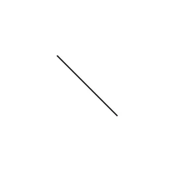 |
Aggregation |
A whole-part relationship represented by a hollow diamond at the source end. | 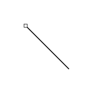 |
Composition |
A strong whole-part relationship represented by a filled diamond at the source end. | 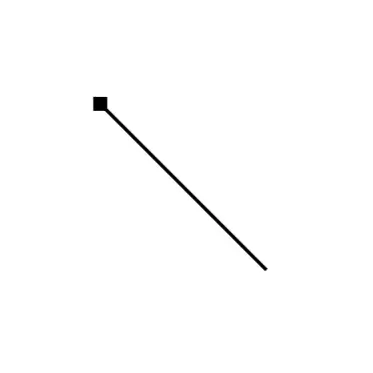 |
Inheritance |
Represents generalization (inheritance) with an open triangle arrowhead at the target end. | 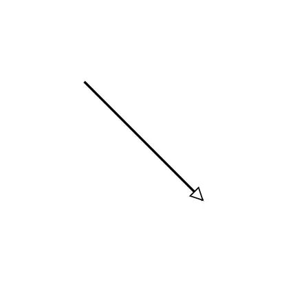 |
Dependency |
Represents a dependency relationship using a dashed arrow. | 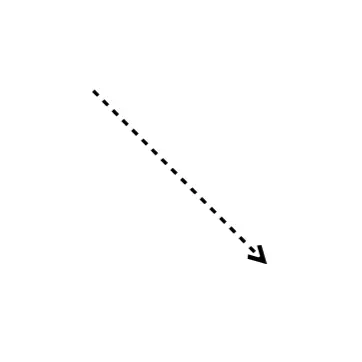 |
Realization |
Represents interface implementation using a dashed line with an open triangle arrowhead. | 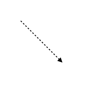 |
@using Syncfusion.Blazor.Diagram

<SfDiagramComponent Height="800px" Connectors="@connectors" />

@code {
    private DiagramObjectCollection<Connector> connectors = new DiagramObjectCollection<Connector>();

    protected override void OnInitialized()
    {
        connectors.Add(new Connector()
        {
            SourcePoint = new DiagramPoint() { X = 100, Y = 100 },
            TargetPoint = new DiagramPoint() { X = 200, Y = 200 },
            Type = ConnectorSegmentType.Straight,
            Shape = new RelationShip() { RelationshipShape = Relationship.Inheritance }
        });
    }
}
The AssociationType property is only applicable when RelationshipShape is set to Relationship.Association.
| Value | Description | Example |
|---|---|---|
AssociationFlow.Directional |
Displays an arrow from the source to the target. | 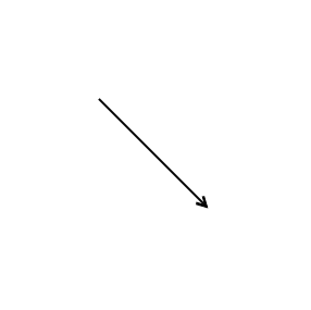 |
AssociationFlow.BiDirectional |
Displays arrows in both directions. | 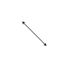 |
using Syncfusion.Blazor.Diagram

<SfDiagramComponent Height="800px" Connectors="@connectors" />

@code {
    private DiagramObjectCollection<Connector> connectors = new DiagramObjectCollection<Connector>();

    protected override void OnInitialized()
    {
        connectors.Add(new Connector()
        {
            SourcePoint = new DiagramPoint() { X = 100, Y = 100 },
            TargetPoint = new DiagramPoint() { X = 200, Y = 200 },
            Type = ConnectorSegmentType.Straight,
            Shape = new RelationShip()
            {
                RelationshipShape = Relationship.Association,
                AssociationType = AssociationFlow.BiDirectional
            }
        });
    }
}
Define Relationship Multiplicity
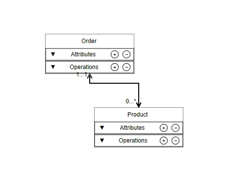
ClassifierMultiplicity defines the multiplicity (cardinality) labels displayed at the source and target ends of a relationship connector. Use the Multiplicity property to specify multiplicity values for both ends of the relationship. The LowerBounds and UpperBounds property specifies the minimum and maximum number of instances. Use "*" to represent an unlimited number of instances.
@using Syncfusion.Blazor.Diagram

<SfDiagramComponent Height="600px" Connectors="@connectors" />

@code {
    DiagramObjectCollection<Connector> connectors = new DiagramObjectCollection<Connector>();

    protected override void OnInitialized()
    {
        connectors.Add(new Connector()
        {
            SourcePoint = new DiagramPoint() { X = 100, Y = 100 },
            TargetPoint = new DiagramPoint() { X = 200, Y = 200 },
            Shape = new RelationShip()
            {
                RelationshipShape = Relationship.Aggregation,
                AssociationType   = AssociationFlow.BiDirectional,
                Multiplicity = new ClassifierMultiplicity()
                {
                    Source = new MultiplicityLabel() { LowerBounds = "1", UpperBounds = "1" },
                    Target = new MultiplicityLabel() { LowerBounds = "0", UpperBounds = "*" }
                }
            }
        });
    }
}
Add UML Shapes to the Symbol Palette
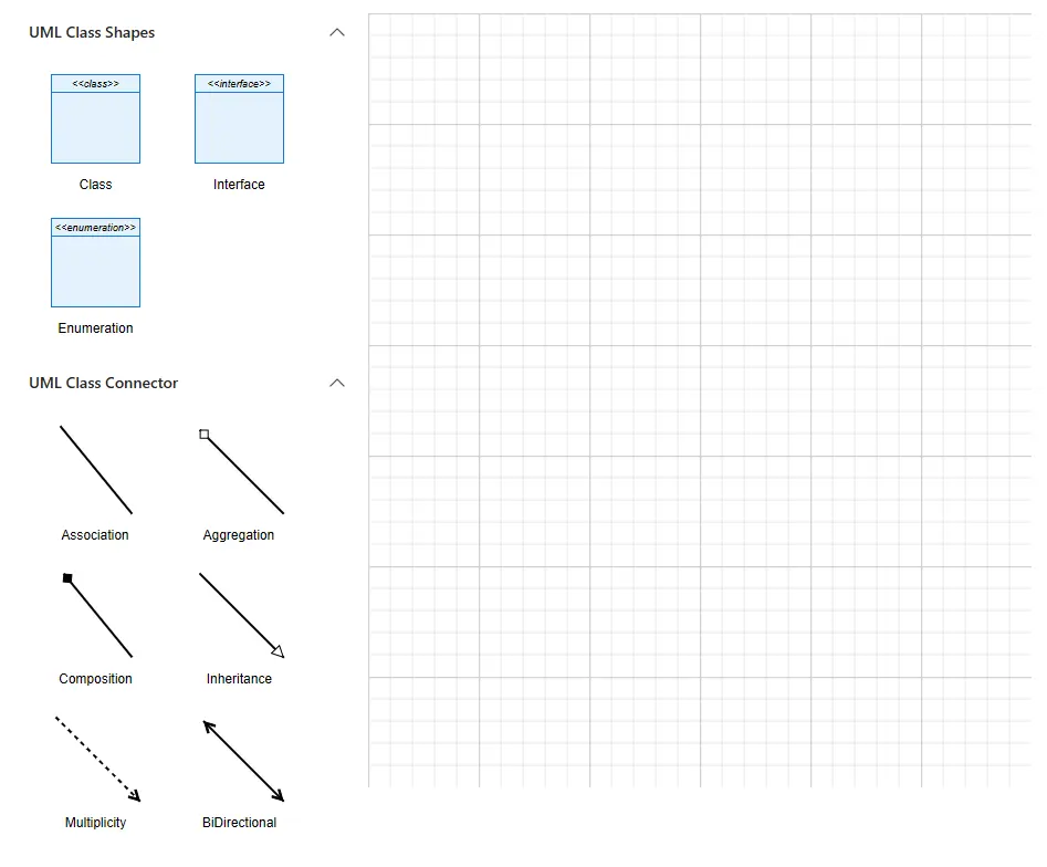
Add UML classifier shapes and relationship connectors to the SfSymbolPaletteComponent so users can drag and drop UML symbols onto the diagram canvas.
@using Syncfusion.Blazor.Diagram
@using Syncfusion.Blazor.Diagram.SymbolPalette

<div style="float:left">
    <SfSymbolPaletteComponent @ref="@palette" Width="320px" Height="900px" Palettes="@palettes" SymbolHeight="@symbolHeight" SymbolWidth="@symbolWidth" />
</div>
<div style="float:left">
        <SfDiagramComponent @ref="@Diagram" Height="700px" Width="600px" />
</div>
@code {
    private SfDiagramComponent Diagram;
    private SfSymbolPaletteComponent palette;
    private DiagramObjectCollection<Palette> palettes;
    double symbolHeight = 130;
    double symbolWidth = 130;
    private DiagramObjectCollection<NodeBase> umlClassNodes { get; set; }
    private DiagramObjectCollection<NodeBase> umlConnectors { get; set; }
    protected override async Task OnAfterRenderAsync(bool firstRender)
    {
        palette.Targets = new DiagramObjectCollection<SfDiagramComponent>
        {
            Diagram
        };
    }
    protected override void OnInitialized()
    {
        palettes = new DiagramObjectCollection<Palette>();
        umlClassNodes = new DiagramObjectCollection<NodeBase>()
        {
            new Node
            {
                Height = 200,
                Shape = new UmlClassifierShape()
                {
                    Classifier = ClassifierShape.Class,
                    ClassShape = new UmlClass()
                    {
                        Name = "ClassName",
                    }
                }
            },
            new Node
            {
                Height = 200,
                Shape = new UmlClassifierShape()
                {
                    Classifier = ClassifierShape.Interface,
                    InterfaceShape = new UmlInterface
                    {
                        Name = "InterfaceName",
                    }
                }
            },
            new Node
            {
                Width = 200,
                Shape = new UmlClassifierShape()
                {
                    Classifier = ClassifierShape.Enumeration,
                    EnumerationShape = new UmlEnumeration
                    {
                        Name = "EnumName",
                    }
                }
            }
        };
        umlConnectors = new DiagramObjectCollection<NodeBase>()
        {
            new Connector
            {
                SourcePoint = new DiagramPoint() { X = 110, Y = 0 }, TargetPoint = new DiagramPoint() { X = 200, Y = 110 },
                Shape = new RelationShip() { RelationshipShape = Relationship.Association }
            }
        };
        palettes = new DiagramObjectCollection<Palette>()
        {
           new Palette()
           {
               ID = "BasicShape", Symbols = umlClassNodes, Title = "UML Class Shapes"
           },
           new Palette()
           {
               ID = "ConnectorShape", Symbols = umlConnectors, Title = "UML Class Connector"
           }
        };
    }
}
A complete working sample can be downloaded from GitHub.