Orthogonal Segments in Blazor Diagram Component
How to Create Orthogonal Segments
Orthogonal segments create segments that are perpendicular to each other. To create an orthogonal connector, set the connector Type to Orthogonal to create a default orthogonal segment. The following code example illustrates how to create a default orthogonal segment.
@using Syncfusion.Blazor.Diagram

<SfDiagramComponent Width="1000px" Height="500px" Connectors="@_connectors">
</SfDiagramComponent>

@code
{
    //Defines diagram's connector collection.
    private DiagramObjectCollection<Connector> _connectors = new DiagramObjectCollection<Connector>();

    protected override void OnInitialized()
    {
        Connector connector = new Connector()
        {
            ID = "connector1",
            SourcePoint = new DiagramPoint()
            {
                X = 100,
                Y = 100
            },
            Style = new ShapeStyle() { StrokeColor = "#6f409f", StrokeWidth = 1 },
            TargetPoint = new DiagramPoint() { X = 200, Y = 200 },
            //Specify the segments type as Orthogonal.
            Type = ConnectorSegmentType.Orthogonal,
            TargetDecorator = new DecoratorSettings()
            {
                Shape = DecoratorShape.Arrow,
                Style = new ShapeStyle()
                {
                    Fill = "#6f409f",
                    StrokeColor = "#6f409f",
                    StrokeWidth = 1
                }
            }
        };
        _connectors.Add(connector);
    }
}
A complete working sample can be downloaded from GitHub
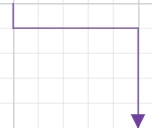
The Length and Direction properties control the segment length and routing direction. The Direction property accepts the following enum values:
| Direction | Description |
|---|---|
| Top | Segment extends upward from the previous point. |
| Bottom | Segment extends downward from the previous point. |
| Left | Segment extends leftward from the previous point. |
| Right | Segment extends rightward from the previous point. |
@using Syncfusion.Blazor.Diagram

<SfDiagramComponent Width="1000px" Height="500px" Connectors="@connectors">
</SfDiagramComponent>

@code
{
    //Defines diagram's connector collection.
    DiagramObjectCollection<Connector> connectors = new DiagramObjectCollection<Connector>();

    protected override void OnInitialized()
    {
        Connector Connector = new Connector()
        {
            ID = "connector1",
            SourcePoint = new DiagramPoint()
            {
                X = 100,
                Y = 100
            },
            Style = new ShapeStyle() { StrokeColor = "#6f409f", StrokeWidth = 1 },
            TargetPoint = new DiagramPoint() { X = 200, Y = 200 },
            Type = ConnectorSegmentType.Orthogonal,
            //Create a new segment with length and direction.
            Segments = new DiagramObjectCollection<ConnectorSegment>()
            {
                new OrthogonalSegment
                {
                    Length = 100,
                    Type = ConnectorSegmentType.Orthogonal,
                    Direction = Direction.Right
                },
                new OrthogonalSegment
                {
                    Length = 100,
                    Type = ConnectorSegmentType.Orthogonal,
                    Direction = Direction.Bottom,
                }
            },
            TargetDecorator = new DecoratorSettings()
            {
                Shape = DecoratorShape.Arrow,
                Style = new ShapeStyle()
                {
                    Fill = "#6f409f",
                    StrokeColor = "#6f409f",
                    StrokeWidth = 1
                }
            }
        };
        connectors.Add(Connector);
    }
}Ensure the connector type and each segment type are both set to Orthogonal. Ensure the connector
Typematches the segmentType.
How to Edit Orthogonal Segments

- Orthogonal thumbs allow adjusting the length of adjacent segments by clicking and dragging.
- Some segments may be added or removed automatically during dragging to preserve proper orthogonal routing between segments.
@using Syncfusion.Blazor.Diagram

<SfDiagramComponent @ref="_diagram" Width="1000px" Height="500px" Connectors="@_connectors">
</SfDiagramComponent>

@code
{
    //Reference the diagram
    private SfDiagramComponent _diagram;
    //Initialize the diagram's node collection.
    private DiagramObjectCollection<Connector> _connectors = new DiagramObjectCollection<Connector>();

    protected override void OnInitialized()
    {
        // Enable the segment editing.
        Connector connector = new Connector()
        {
            ID = "Connector2",
            Constraints = ConnectorConstraints.Default | ConnectorConstraints.DragSegmentThumb,
            Type = ConnectorSegmentType.Orthogonal,
            SourcePoint = new DiagramPoint { X = 400, Y = 100 },
            TargetPoint = new DiagramPoint { X = 500, Y = 200 }
        };
        _connectors.Add(connector);
    }
}
A complete working sample can be downloaded from GitHub
How to Customize Orthogonal Segment Thumb Shape
The Orthogonal connector can have multiple segments between the source and target points. By default, segment thumbs are rendered as circles. They can be customized globally or per connector using the SegmentThumbSettings class.
To change the segment thumb shape for all Orthogonal connectors, configure the ConnectorSegmentThumb property of the SfDiagramComponent and set the Shape property to the desired shape.
To customize the segment thumb shape for a specific connector, first disable the InheritSegmentThumbShape constraint. Then, configure the SegmentThumbSettings property of the Connector class, specifying the desired shape using the Shape property of the SegmentThumbSettings class.
The following predefined shapes are available for segment thumbs:
| Shape name | Shape |
|---|---|
| Rhombus | 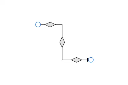 |
| Square | 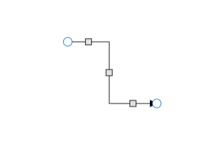 |
| Rectangle | 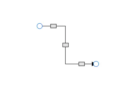 |
| Ellipse | 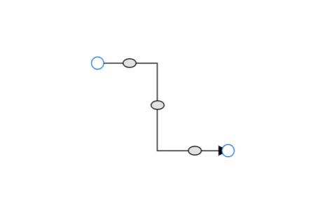 |
| Circle | 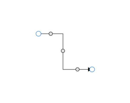 |
| Arrow | 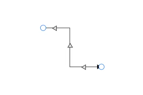 |
| OpenArrow | 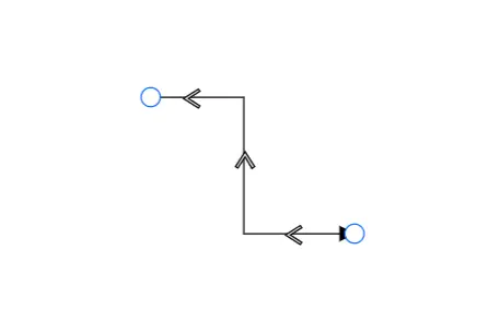 |
| Fletch | 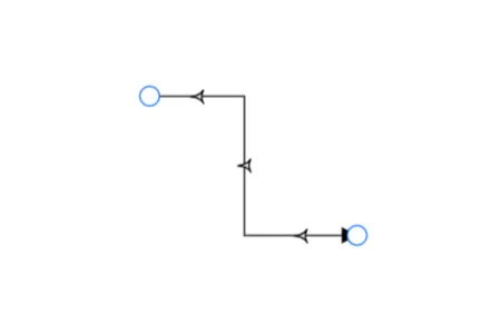 |
| OpenFletch | 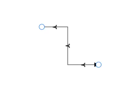 |
| IndentedArrow | 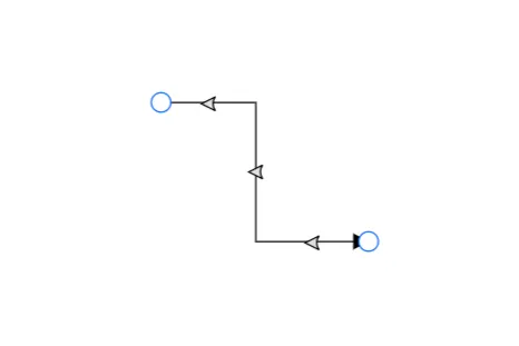 |
| OutdentedArrow | 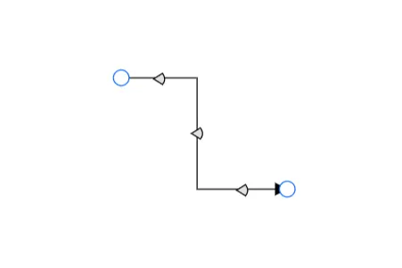 |
| DoubleArrow | 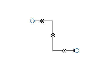 |
The following code example illustrates how to customize the orthogonal segment thumb shape.
@using Syncfusion.Blazor.Diagram

<SfDiagramComponent @ref="_diagram" Width="1000px" Height="500px" Connectors="@_connectors">
</SfDiagramComponent>

@code
{
    private SfDiagramComponent _diagram;
    private DiagramObjectCollection<Connector> _connectors = new DiagramObjectCollection<Connector>();

    protected override void OnInitialized()
    {
        Connector connector = new Connector()
        {
            ID = "Connector2",
            Constraints = ConnectorConstraints.Default | ConnectorConstraints.DragSegmentThumb,
            Type = ConnectorSegmentType.Orthogonal,
            SourcePoint = new DiagramPoint { X = 400, Y = 100 },
            TargetPoint = new DiagramPoint { X = 500, Y = 200 },
            SegmentThumbSettings = new SegmentThumbSettings() { Shape = SegmentThumbShapes.IndentedArrow }
        };
        _connectors.Add(connector);
    }
}
A complete working sample can be downloaded from GitHub.
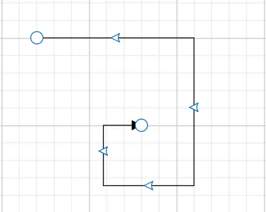
When the InheritSegmentThumbShape constraint is enabled in the connector, the shape specified at the diagram level will be applied to the connector’s segment thumb. This allows for consistent segment thumb shapes across the diagram.
The following code example illustrates how to customize the orthogonal segment thumb shape using InheritSegmentThumbShape constraints.
@using Syncfusion.Blazor.Diagram

<SfDiagramComponent @ref="_diagram" Width="1000px" Height="500px" Connectors="@_connectors" ConnectorSegmentThumb="@_segmentThumbSettings">
</SfDiagramComponent>

@code
{
    private SfDiagramComponent _diagram;
    private DiagramObjectCollection<Connector> _connectors = new DiagramObjectCollection<Connector>();
    private SegmentThumbSettings _segmentThumbSettings = new SegmentThumbSettings() { Shape = SegmentThumbShapes.Fletch };

    protected override void OnInitialized()
    {
        Connector connector = new Connector()
        {
            ID = "Connector2",
            Constraints = ConnectorConstraints.Default | ConnectorConstraints.DragSegmentThumb | ConnectorConstraints.InheritSegmentThumbShape,
            Type = ConnectorSegmentType.Orthogonal,
            SourcePoint = new DiagramPoint { X = 400, Y = 100 },
            TargetPoint = new DiagramPoint { X = 500, Y = 200 }
        };
        _connectors.Add(connector);
    }
}
A complete working sample can be downloaded from GitHub
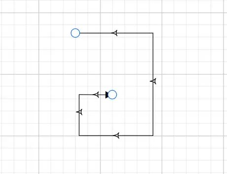
Note: This feature ensures that the shape is updated regardless of whether the InheritSegmentThumbShape enum value is added to the Constraints property of the diagram. If you apply the
InheritSegmentThumbShapeconstraints, the shape will be updated at the diagram level. Without these constraints, the shape will be updated at the connector level.
Note: To make the shapes visible, ensure that the DragSegmentThumb enum is added to the connector’s constraints.