Annotation in ASP.NET Core Diagram
Annotation is a block of text that can be displayed over a node or connector. Annotation is used to textually represent an object with a string that can be edited at runtime. Multiple annotations can be added to a node/connector.
Create annotation
An annotation can be added to a node/connector by defining the annotation object and adding that to the annotation collection of the node/connector. The content property of annotation defines the text to be displayed.
Add annotations at runtime
-
Annotations can be added at runtime by using the client-side method
addLabels. -
The annotation’s
IDproperty is used to define the name of the annotation and its further used to find the annotation at runtime and do any customization.
var diagramElement = document.getElementById('element');
var diagram = diagramElement.ej2_instances[0];
var annotation = [{
    id: 'label1',
    //set the contect
    content: 'Annotation'
}]
//Method to add labels at run time
diagram.addLabels(diagram.nodes[0], annotation);
diagram.dataBind();
Remove annotation
A collection of annotations can be removed from the node by using client-side method removeLabels.
var diagramElement = document.getElementById('element');
var diagram = diagramElement.ej2_instances[0];
var annotation = [{
    id: 'label1',
    content: 'Annotation'
}]
//Method to remove labels at runtime
diagram.removeLabels(diagram.nodes[0], annotation);
Update annotation at runtime
You can change any annotation properties at runtime and update it through the client-side method dataBind.
var diagramElement = document.getElementById('element');
var diagram = diagramElement.ej2_instances[0];

diagram.nodes[0].annotations[0].content = 'Updated Annotation';
//Method to update the annotation at run time
diagram.dataBind();
Alignment
Annotation can be aligned relative to the node boundaries. It has margin, offset, horizontal, and vertical alignment settings. It is quite tricky when all four alignments are used together but gives more control over alignment.
Offset
The offset property of annotation is used to align the annotations based on fractions. 0 represents top/left corner, 1 represents bottom/right corner, and 0.5 represents half of width/height.
Set the size for nodes annotation by using width and height properties.
Horizontal and vertical alignment
The horizontalAlignment property of annotation is used to set how the annotation is horizontally aligned at the annotation position determined from the fraction values. The verticalAlignment property is used to set how annotation is vertically aligned at the annotation position.
The following tables illustrates all the possible alignments visually with ‘offset (0, 0)’.
| Horizontal Alignment | Vertical Alignment | Output with Offset(0,0) |
|---|---|---|
| Left | Top | 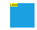 |
| Center | Top | 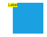 |
| Right | Top | 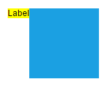 |
| Left | Center | 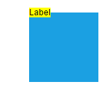 |
| Center | Center | 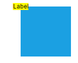 |
| Right | Center | 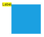 |
| Left | Bottom | 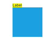 |
| Center | Bottom | 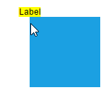 |
| Right | Bottom | 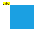 |
Annotation alignment with respect to segments
The offset and alignment properties of annotation allows to align the connector annotations with respect to the segments.
Margin
Margin is an absolute value used to add some blank space in any one of its four sides. The annotations can be displaced with the margin property. The following code example illustrates how to align a annotation based on its offset, horizontalAlignment, verticalAlignment, and margin values.
Text align
The textAlign property of annotation allows to set how the text should be aligned (left, right, center, or justify) inside the text block.
Hyperlink
ASP.NET Core Diagram provides a support to add a hyperlink for the nodes/connectors annotation. It can also be customized.
A user can open the hyperlink in the new window, the same tab and the new tab by using the hyperlinkOpenState property.
Template Support for Annotation
ASP.NET Core Diagram provides template support for annotation. You should define a SVG/HTML content as string in the annotation’s template property.
Wrapping
When text overflows node boundaries, you can control it by using text wrapping. So, it is wrapped into multiple lines. The wrapping property of annotation defines how the text should be wrapped.
| No Wrap | Text will not be wrapped. | 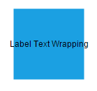 |
| Wrap | Text-wrapping occurs, when the text overflows beyond the available node width. | 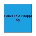 |
| WrapWithOverflow (Default) | Text-wrapping occurs, when the text overflows beyond the available node width. However, the text may overflow beyond the node width in the case of a very long word. | 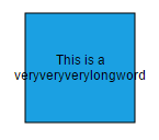 |
Text overflow
The label’s TextOverflow property is used control whether to display the overflowed content in node or not.
Appearance
-
You can change the font style of the annotations with the font specific properties (fontSize, fontFamily, color).
-
The label’s
bold,italic, andtextDecorationproperties are used to style the label’s text. -
The label’s
fill,strokeColor, andstrokeWidthproperties are used to define the background color and border color of the annotation and theopacityproperty is used to define the transparency of the annotations. -
The
visibleproperty of the annotation enables or disables the visibility of annotation.
The fill, border, and opacity appearances of the text can also be customized with appearance specific properties of annotation.
Interaction
ASP.NET Core Diagram allows annotation to be interacted by selecting, dragging, rotating, and resizing. Annotation interaction is disabled, by default. You can enable annotation interaction with the constraints property of annotation. You can also curtail the services of interaction by enabling either selecting, dragging, rotating, or resizing individually with the respective constraints property of annotation.
Edit
ASP.NET Core Diagram provides support to edit an annotation at runtime, either programmatically or interactively. By default, annotation is in view mode. But it can be brought to edit mode in two ways;
-
Programmatically - By using
startTextEditmethod, edit the text through programmatically. -
Interactively
- By double-clicking the annotation.
- By selecting the item and pressing the F2 key.
Double-clicking any annotation will enable editing and the node enables first annotation editing. When the focus of editor is lost, the annotation for the node is updated. When you double-click on the node/connector/diagram model, the doubleClick event gets triggered.
Read-only annotations
ASP.NET Core Diagram allows to create read-only annotations. You have to set the read-only property of annotation to enable/disable the read-only constraints.
Drag Limit
-
The ASP.NET Core Diagram control now supports defining the
dragLimitto the label while dragging from the connector and also update the position to the nearest segment offset. -
You can set the value to dragLimit
left,right,top, andbottomproperties which allows the dragging of connector labels to a certain limit based on the user defined values. -
By default, drag limit will be disabled for the connector. It can be enabled by setting connector constraints as drag.
Multiple annotations
You can add any number of annotations to a node or connector.
Constraints
The constraints property of annotation allows to enable or disable certain annotation behaviours. For instance, you can disable annotation editing.
Annotation rotation
The rotationReference property of an annotation allows you to control whether the text should rotate relative to its parent node or the Page. The following code examples illustrate how to configure rotationReference for an annotation.
var diagramElement = document.getElementById('element');
var diagram = diagramElement.ej2_instances[0];
var annotation = [{
    id: 'label1',
    content: 'Annotation',
    //To disable annotation rotation
    rotationReference: 'Page'
}]
diagram.dataBind();| Value | Description | Image |
|---|---|---|
| Page | When this option is set, the annotation remains fixed in its original orientation even if its parent node is rotated. | 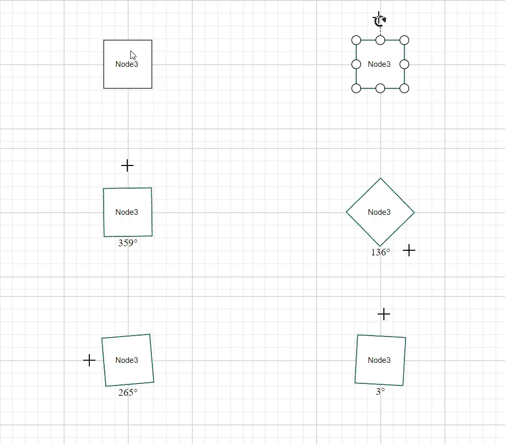 |
| Parent | In this case, the annotation rotates along with its parent node. | 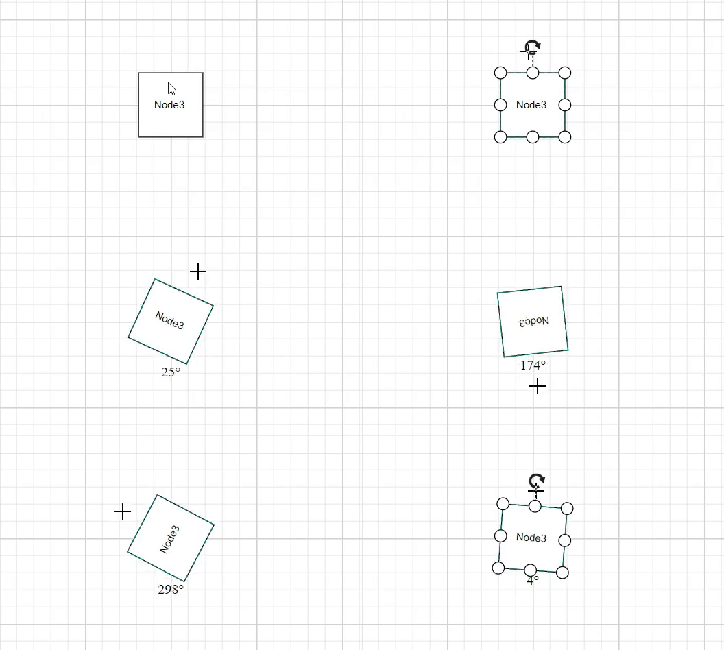 |